PN 305200901, Rev YT
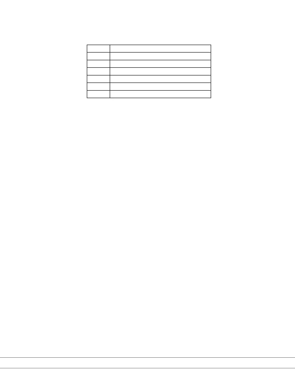
Register #25 is a MODBUSCommand register. This register allows sending spe-
cial commands to the 3050 Analyzer as shown below.
Value Command Description
71 Start Verication
76 Load Sensor Memory
81 Quit Verication
82 Reset Analyzer
84 Start/Stop Test Mode
90 Start Zero Calibration
The last set of registers starting from #141 represents ASCII strings. Each reg-
ister is holding two ASCII characters. End of the string should be marked with
integer number of zero (‘’). For example, if the AnalyzerName variable is set to
“Dev”, the holding register values are (considering that high byte located rst)
#141 (68, 101) and #142 (118, 0). Note that zero (‘’) indicates the end of the
ASCII string.
ID/Status Information
The Modbus master can poll the analyzer periodically for status information
via Modbus function 17 (11Hex). The returned information has the following
format:
1 byte Slave ID = 50h for 3050-OLV Analyzer
1 byte Run Status = FFh for Analyzer Online
(invalid signal = 0)
= 00h for Analyzer Oine
(invalid signal = 1)
2 bytes Status Word = System State which is Register 8
The most signicant byte comes rst.
15 bytes Model Name = Analyzer Model Name are Registers 213–220
12 bytes Serial Number = Analyzer Serial Number located in
Registers 183–189
4 bytes Version Number = S200 located in Register 82
The byte count is 35 (23Hex).
6-10 | 3050-OLV Moisture Analyzer

 Loading...


