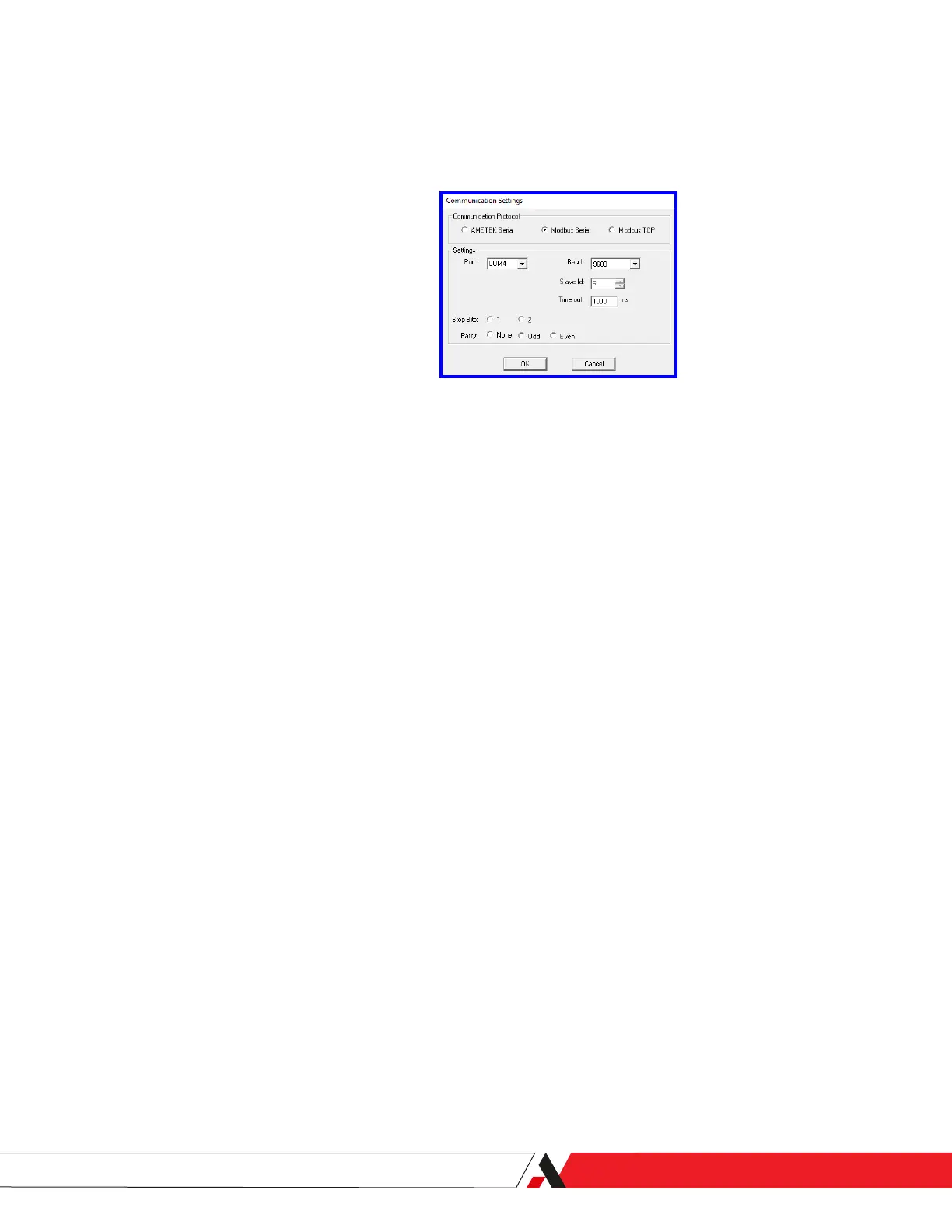
Figure 3-2.2.
PC Serial Communication
Settings dialog box (Modbus
Serial selected).
Settings
Port
Select the COM port on your computer where the connection to the
analyzer is installed.
Baud (Rate)
Select the baud rate at which data will be transferred.
Slave Id
This is the Modbus® slave address of the analyzer, where 0 = Disabled
and 1–255 = Enabled. If using the RS-232 port, the address setting is
not applicable (it is greyed out).
If using the RS-485 port, enter a unique Modbus address (Slave ID) for
the analyzer.
Time out (ms)
Time out value (duration) that the software will use to attempt to
establish communications with the analyzer. AMETEK recommends a
value of 1000 ms.
Stop Bits
Select the number of stop bits (1 or 2) of the Modbus network.
Parity
Select the parity of the Modbus network (None, Odd, or Even).
Modbus Serial Communication Setup
When you select the Modbus Serial communication option (Figure 3-2.2), the
following parameter settings are available:
PN 305200901, Rev YT
Controller/Interface | 3-7

 Loading...


