PN 305200901, Rev YT
The cable should be shielded with single twisted pair.
Cable shields should be connected to both the analyzer and the DCS.
If this is not possible, cable shields should be tied to the chassis at each
3050-OLV. If this is not possible, tie the shield at the PC or DCS to chassis
and remaining shield to the chassis through a 0.1 mF @ 500 V capacitor.
The 3050-OLV Analyzer signal common is connected to earth ground.
If the analog output is also grounded, the analog output will no lon-
ger be electrically isolated. Contact AMETEK if this situation occurs.
Analyzer power must be removed when connecting or disconnecting
the 4–20 mA signal.
The 4–20 mA loop circuit must have a load resistance of between
100–500 ohms or malfunction may occur. If a loop check is performed,
a 100 ohm resistor must be placed in series with the ammeter.
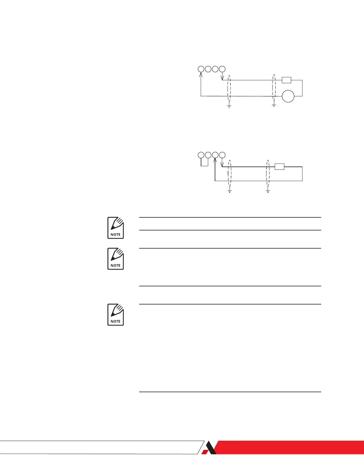
4-20 mA Output, Loop Powered (TB-2)
3 4 5 6
3 4 5 6
4-20 mA Output, Self Powered (TB-2)
R
Load
+ -
External 24V DC
Supply
+
-
R
Load
+
-
4-20 mA Output Wiring
Notes
1. Cable should be shielded with single twisted pair.
2. Cable shields should be connected to both the analyzer and the DCS. If this is not
possible, cable shields should be tied to the chassis at each 3050-OLV. If this is not
possible, tie the shield at the PC or DCS to chassis and remaining shield to the chassis
through a 0.1 mF @ 500V capacitor
100 to 500 W
100 to 500 W
3. The 3050-OLV signal common is connected to earth ground. If the analog output is also
grounded, the analog output will no longer be electrically isolated. Contact AMETEK if
this situation occurs.
Analyzer power must be removed when connecting or disconnecting the 4-20 mA signal.
The 4-20 mA loop circuit must have a load resistance of between 100 and 500 ohms or
malfunction may occur. If a loop check is performed, the resistor must be placed in series
with the ohmmeter.
Figure 2-6.
3050-OLV Analyzer Power and
Signal Connections.
4–20 mA Output Wiring
Installation and Start-Up | 2-13

 Loading...


