General Information 1-4 Remote Programming Setup and Interface
S412E PM PN: 10580-00319 Rev. N 1-3
other. A single LAN that is not connected to other LANs requires a default gateway
setting of 0.0.0.0. If you have a gateway, then the default gateway would be set to the
appropriate value of your gateway
• Ethernet Address: An Ethernet address is a unique 48-bit value that identifies a
network interface card to the rest of the network. Every network card has a unique
ethernet address (MAC address) permanently stored into its memory.
Interface between the LMR Master and other devices on the network is via a category five
(CAT-5) interface cable connected to a network. This cable uses four twisted pairs of insulated
copper wires terminated into an RJ45 connector. CAT-5 cabling is capable of supporting
frequencies up to 100 MHz and data transfer speeds up to 1 Gbps, which accommodates
1000Base-T, 100Base-T, and 10Base-T networks. CAT-5 cables are based on the EIA/TIA 568
Commercial Building Telecommunications Wiring Standard developed by the Electronics
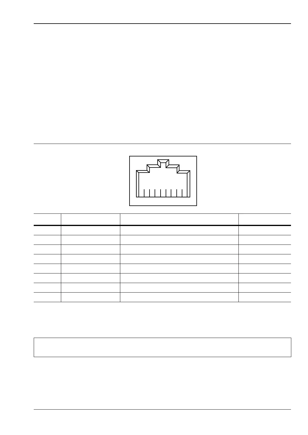
Industries Association. A pinout diagram is shown in Table 1-1.
TCP/IP connectivity requires setting up the parameters described at the beginning of this
section. The following is a brief overview of how to set up a general LAN connection on the
S412E.
Table 1-1. 8-pin Ethernet RJ45 Connector Pinout Diagram
Pin Name Description Wire Color
1 TX+ Transmit data (> +3 volts) White/Orange
2 TX– Transmit data (< –3 volts) Orange
3 RX+ Receive data (> +3 volts) White/Green
4 – Not used (common mode termination) Blue
5 – Not used (common mode termination) White/Blue
6 RX– Receive data (< –3 volts) Green
7 – Not used (common mode termination) White/Brown
8 – Not used (common mode termination) Brown
Note
You may need to consult your network documentation or network administrator for
assistance in configuring your network setup.