Host Application Objects 175 (258)
Anybus CompactCom Sync and PROFINET Isochronous Mode
The sync functionality is described differently in the PROFINET network specification than how it is described
in the specification for Anybus CompactCom in general. See the Anybus CompactCom 40 Software Design
Guide for a detailed description of the Anybus CompactCom sync functionality.
This section describes the correlation between the specifications
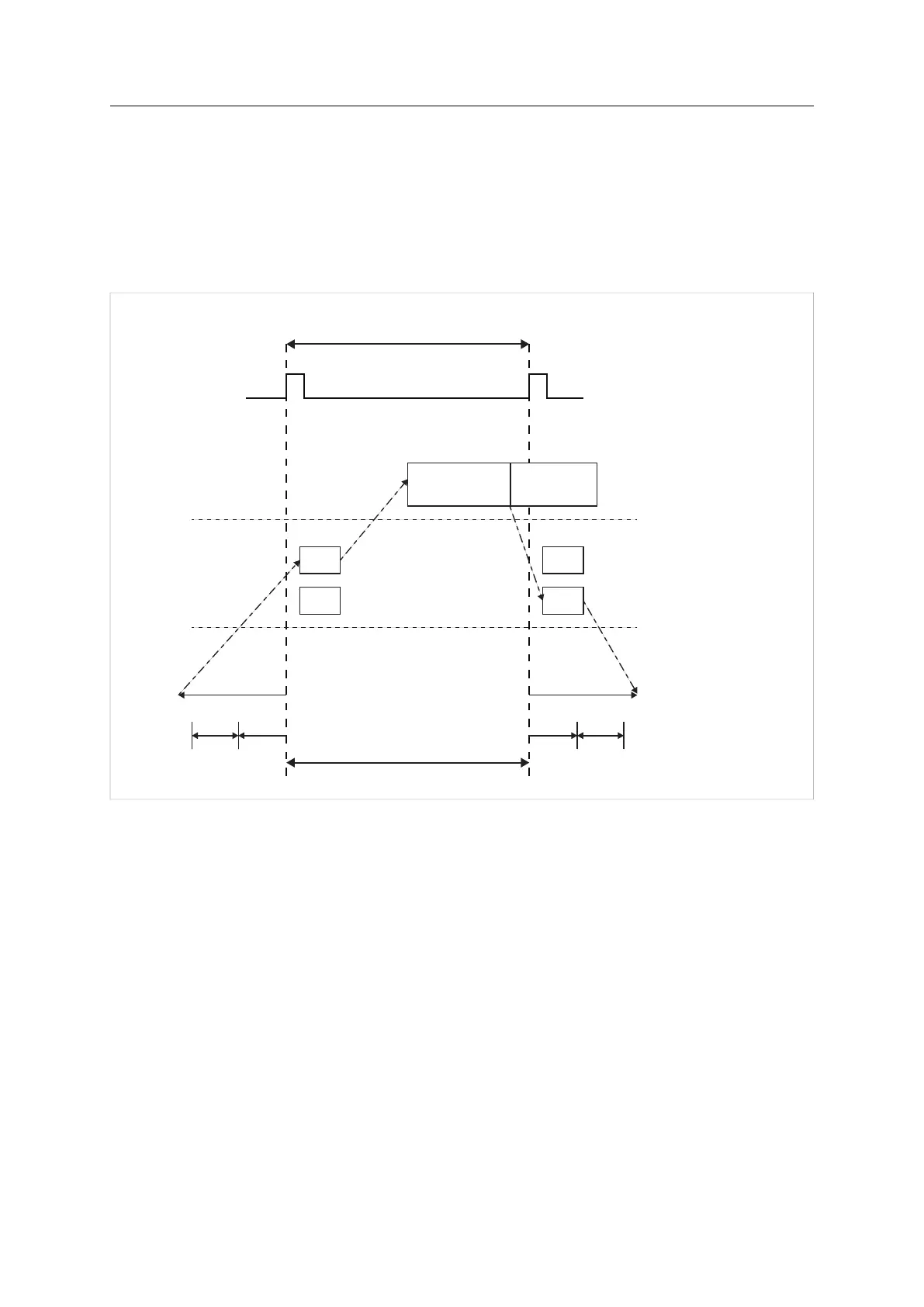
The figure below shows a timing diagram for PROFINET isochronous mode.
Controller Application Cycle (CACF=1)
Application Background
Input
Data
Output
Data
Input
Data
Output
Data
IO controller
IO device
Network
T_DC
T_IO_Input
T_IO_Output
1: T_IO_InputMin
2: T_IO_InputValid
3: T_IO_OutputValid
4: T_IO_OutputMin
41 2 3
Fig. 12
T_IO_OutputMin
T_IO_OutputMin consists of two delays:
• The delay added by the Anybus CompactCom. This is the time from when the message is available on
the network until it is available to the application. This delay is 0 in the current implementation.
• The delay added by the application. This is the time it takes for the application from when it is notified that
new process data has arrived, to when the process data is copied and the output is valid. This delay must
be measured by the application designer. The measured value shall be written to Attribute #4 (Output
Processing).
The value of T_IO_OutputMin must be entered in the GSD file for every submodule supporting synchronous
operation. See example GSD entries below.
Anybus
®
CompactCom
™
40 PROFINET IRT Network Guide SCM-1202-023 EN 1.8