Appendix E: Technical Specification 218 (258)
E.1.7 Ethernet Interface (RJ45 connectors)
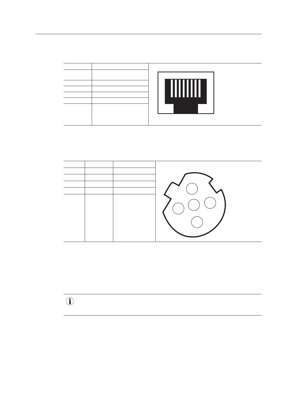
The Ethernet interface operates at 100 Mbit, full duplex, as required by PROFINET.
Pin no Description
4,5,7,8 Connected to chassis ground
over serial RC circuit
6 RD-
3 RD+
2 TD-
1 TD+
Housing Cable Shield
For information on how to connect the PROFINET cable, see Functional Earth (FE) Require-
ments, p. 218
E.1.8 M12 Connectors, Code D
Pin Name Description
1 TXD+ Transmit positive
2 RXD+ Receive positive
3 TXD- Transmit negative
4 RXD- Receive negative
5
(Thread)
Shield Shield
E.2 Functional Earth (FE) Requirements
In order to ensure proper EMC behavior, the module must be properly connected to functional
earth via the FE pad/FE mechanism described in the Anybus CompactCom 40 Hardware
Design Guide. Proper EMC behavior is not guaranteed unless these FE requirements are
fulfilled.
The shield of the RJ45 connector is not connected directly to FE. As all nodes in a PROFINET
network have to share chassis ground connection, the PROFINET cable shield has to be con-
nected to the chassis ground at each node in the network.
For further information, see PROFINET Installation Guideline for Cabling and Assembly, avail-
able for download at www.profinet.com.
E.3 Power Supply
E.3.1 Supply Voltage
The Anybus CompactCom 40 PROFINET IRT requires a regulated 3.3 V power source as
specified in the general Anybus CompactCom 40 Hardware Design Guide.
Anybus
®
CompactCom
™
40 PROFINET IRT Network Guide SCM-1202-023 EN 1.8