Appendix E: Technical Specification 216 (258)
E Technical Specification
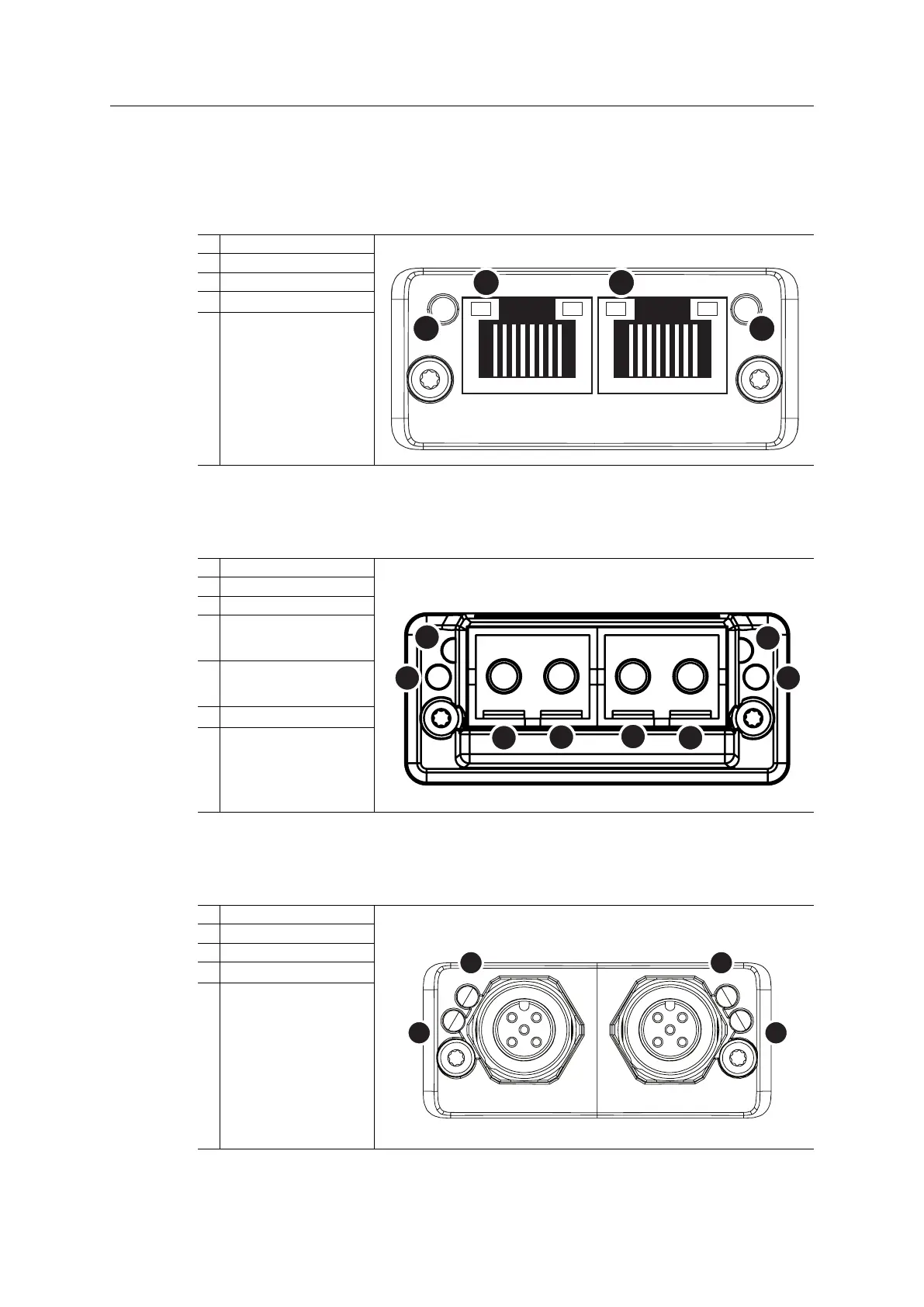
E.1 Front View
E.1.1 Front View (PROFINET IRT, Ethernet Connectors)
#
Item
1
Network Status LED
2
Module Status LED
3
Link/Activity LED (port 1)
4
Link/Activity LED (port 2)
Test sequences are performed on the Network and Module Status LEDs during startup.
E.1.2 Front View (Fiber Optics Connectors)
#
Item
1
Network Status LED
2
Module Status LED
3
Optical signal from the
Anybus CompactCom
module
4
Optical signal to the Any-
bus CompactCom
module
5
Link/Activity LED (port 1)
6
Link/Activity LED (port 2)
Test sequences are performed on the Network and Module Status LEDs during startup.
E.1.3 Front View (M12 Connectors)
#
Item
1
Network Status LED
2
Module Status LED
3
Link/Activity LED (port 1)
4
Link/Activity LED (port 2)
Test sequences are performed on the Network and Module Status LEDs during startup.
Anybus
®
CompactCom
™
40 PROFINET IRT Network Guide SCM-1202-023 EN 1.8