Host Application Objects 177 (258)
Instance Attributes (Instance #1)
# Name Access Corresponding
term for PROFINET
Data Type Value
1 Cycle time Get/Set T_DC UINT32 Application cycle time in nanoseconds
2 Output valid Get/Set T_IO_Output UINT32 Output valid point relative to SYNC events,
in nanoseconds
Default value: 0
3 Input capture Get/Set T_DC - T_IO_Input UINT32 Input capture point relative to SYNC events,
in nanoseconds
Default value: 0
4 Output processing Get T_IO_OutputMin UINT32 Minimum required time, in nanoseconds,
between RDPDI interrupt and “Output valid”
5 Input processing Get T_IO_InputMin - 12
µs
UINT32 Maximum required time, in nanoseconds,
from “Input capture” until write process data
has been completely written to the Anybus
CompactCom module
6 Min cycle time Get T_DC_Min UINT32 Minimum cycle time supported by the appli-
cation, in nanoseconds
7
Sync mode Get/Set
-
UINT16 This attribute is used to select synchroniza-
tion mode. It enumerates the bits in attribute
8
0: Nonsynchronous mode. (Default value if
nonsynchronous mode is supported)
1: Synchronous mode
2 - 65535: Reserved. Any attempt to set
sync mode to an unsupported value shall
generate an error response
8 Supported sync
modes
Get
-
UINT16 A list of the synchronization modes the ap-
plication supports.
Each bit corresponds to a mode in attribute
7
Bit 0: 1 = Nonsynchronous mode supported
Bit 1: 1 = Synchronous mode supported
(Required for synchronous application)
Bit 2 - 15: Reserved (0)
9 Control Task cycle
factor
Get/Set CACF (Controller Ap-
plication Cycle
Factor)
UINT16 If the synchronous control task operates at
a cycle that is longer than the data cycle
(see attribute #1, Cycle time) then this at-
tribute provides a scaling factor for the cycle
time such that:
Control task duration = Control task cycle
factor x Cycle time.
The information may be used e.g. to inter-
polate output values, if required by the proc-
ess. Note that synchronization to the
Control Task cycle must be done by the host
application.
Default: 1
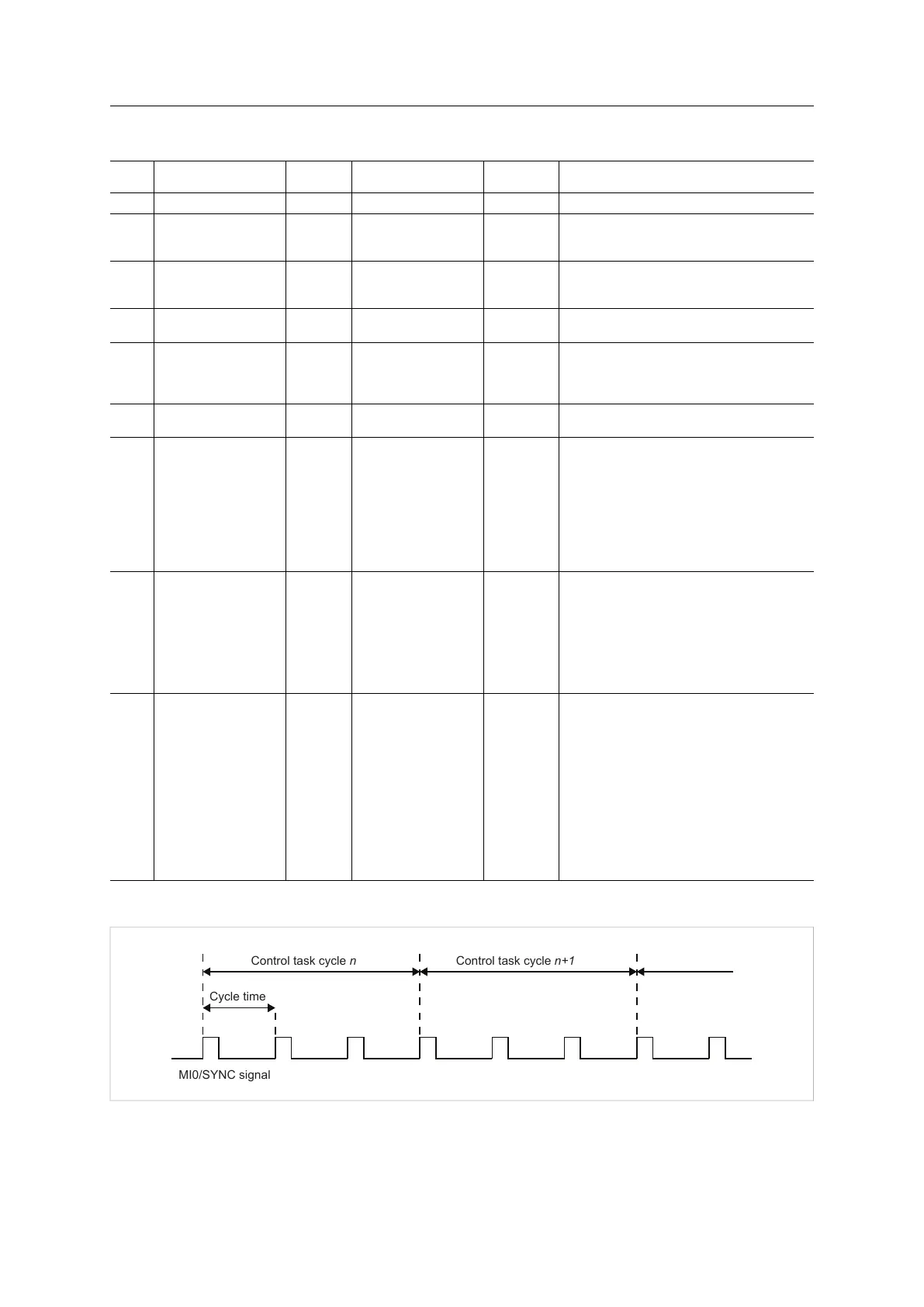
The figure below shows an example of Control Task cycle and Cycle time, with Control Task cycle factor = 3
MI0/SYNC signal
Cycle time
Control task cycle n Control task cycle n+1
Fig. 13
Anybus
®
CompactCom
™
40 PROFINET IRT Network Guide SCM-1202-023 EN 1.8