10
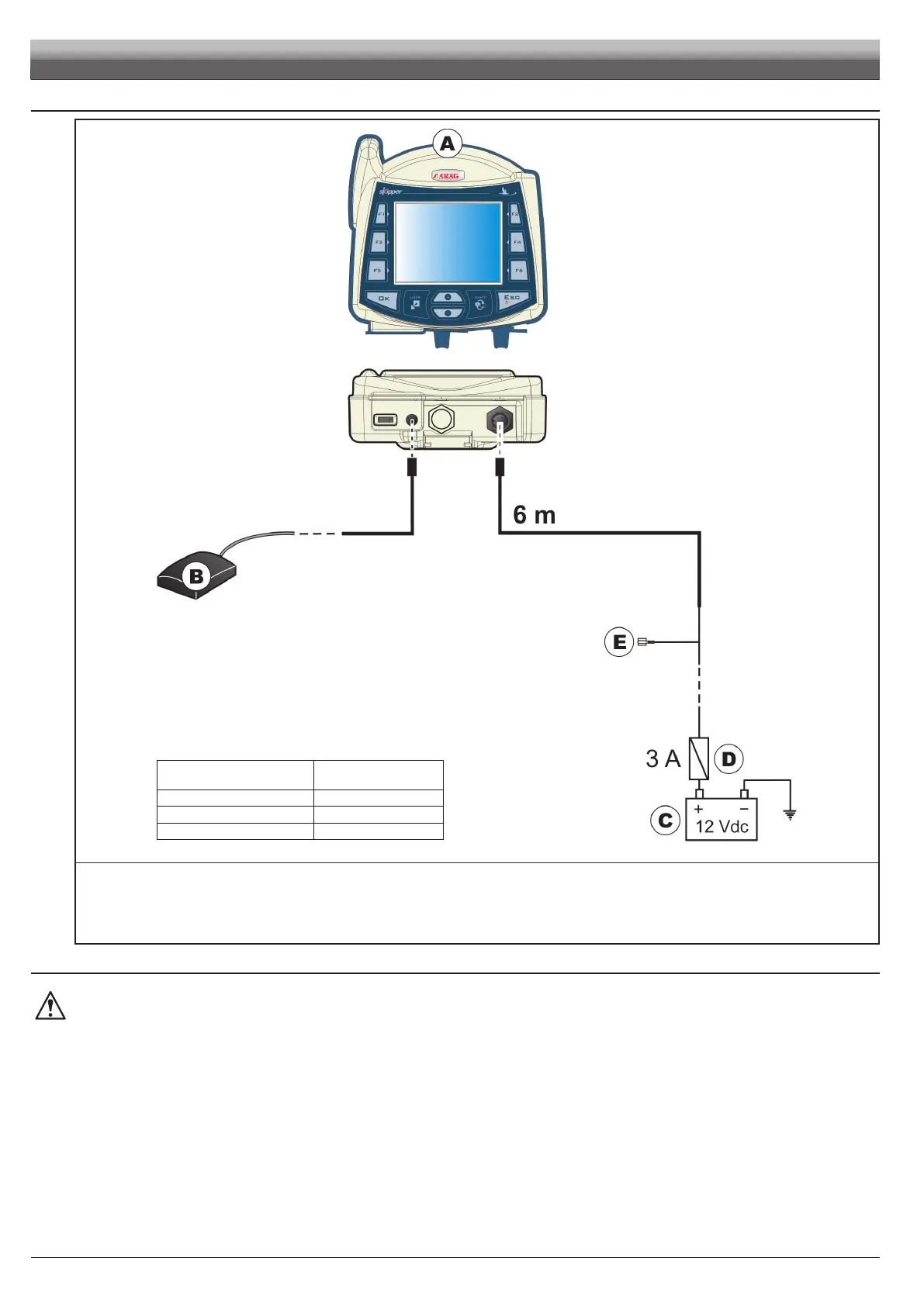
5.7 Electricalconnections-generaldiagram
WIRECOLOR
(POWERCABLE)
RESPECTIVE
CONNECTION
black negative
red positive
green treatment status signal
Fi g. 10
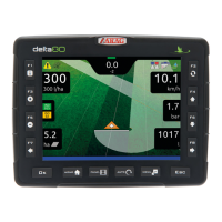
A Satellite navigator
B GPS Antenna
C Battery
D Automotive fuse - 3 A
E Treatment status signal +12 Vdc (from main control valve)
5.8 ConnectiontotheGPSantenna
OnlyusethespecicARAGGPSantennatobeusedinconnectionwithSKIPPERLT.
ARAGshallnotbeheldliableforlossordamageduetouseofdifferenttypesofantenna.
Beforemakingtheconnection,carefullyreadpar.4.3-GeneralprecautionsforlocatingtheSKIPPERLTandcableruns.
Connect the external GPS antenna to Skipper LT.
The connection points are given in par. 4.7 - Electrical connections - general diagram.
INSTALLATION