EFD1000 Installation Manual
DOCUMENT # A-01-126-00 PAGE 100-225 Revision H
© Copyright 2009 Aspen Avionics Inc.
Over Braid or
Double Shield
Over Braid or
Double Shield
Over Braid or
Double Shield
EFD1000
GPS/VLOC RX2A
GPS/VLOC RX2B
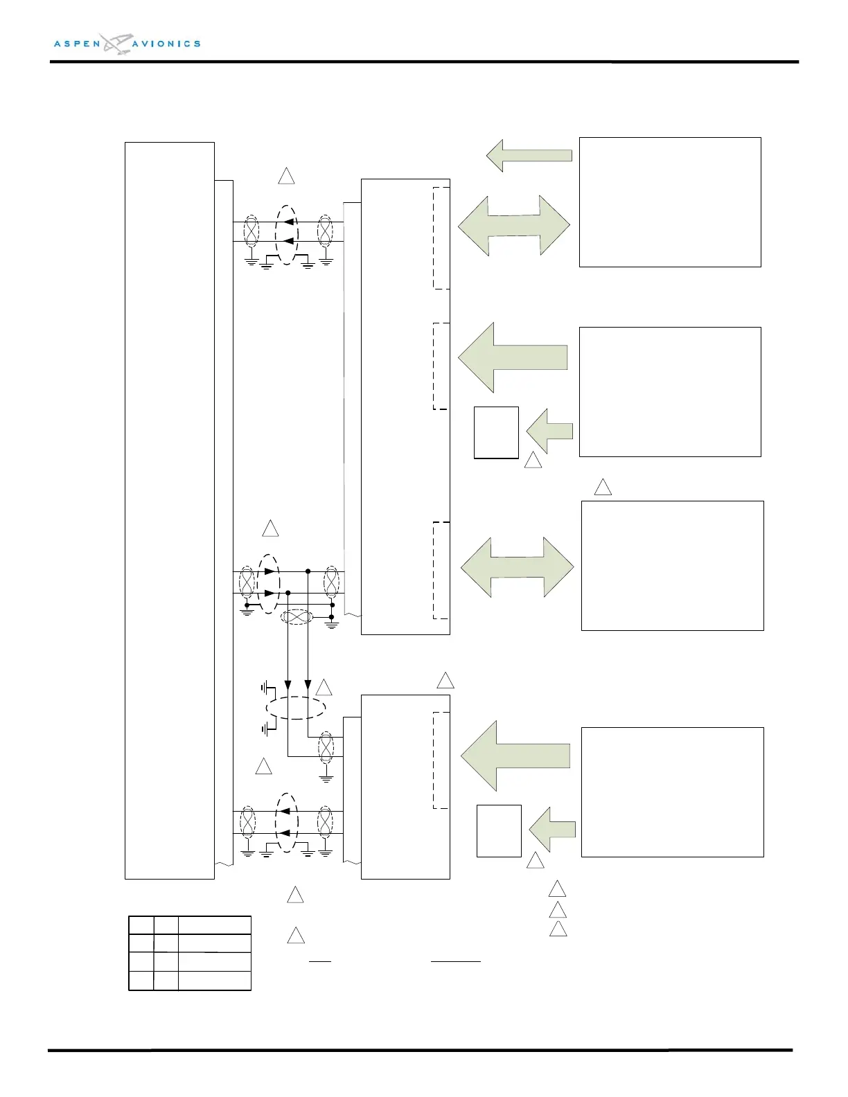
Figure 9.11 Pro Legacy GPS & Dual Analog VLOC
with and w/o Autopilot Interface
ACU #1
P3
18
19
26
27
14
1
15
2
PFD 429 TX1A
PFD 429 TX1B
Autopilot - optional
See Figure:
9.16 for Bendix King
9.17 for S-TEC
9.18 for Century
9.19 for Cessna ARC
9.20 – 9.23A Flight Director
429 RX1B
429 RX1A
429 TX1B
429 TX1A
G
P
S
I
N
P
U
T
22
23
A
U
T
O
P
I
L
O
T
Analog VLOC #2
RS-232/Analog GPS #1
See Figure:
9.12 for KLN89/B & KLN94
9.13 for KLN-90/A/B
9.14 for GX-50/60 & GX-55/65
429 VLOC RX4A
429 VLOC RX4B
RS-232 Flight Plan
To
EFD1000
Pin 8
Analog VLOC #1
ACU #2
14
1
15
2
P3
429 RX1A
429 RX1B
Optional
Back-Up
Nav
Indicator
Optional
Back-Up
Nav
Indicator
V
L
O
C
#
2
V
L
O
C
#
1
429 TX1B
429 TX1A
Autopilot must be connected to ACU #1
See Figure 9.24, 9.25, 9.26 for Back-Up
NAV recommendations. If no GPS installed then
One
backup NAV indicator is required.
2
2
1
2
3
4
Omit ACU #2 if using only 1 Analog Nav.
1
ID#1
Description
G
H
H
ID#2
NONE
NONE
D
GPS1, No NAV1,
No NAV2
GPS1,NAV1,
No NAV2
GPS1, NAV1, NAV2
See Figure 9.15 for:
KX-155(A) &165(A)
KN-53
KX-170A/170B/175/175B
SL-30
See Figure 9.15 for:
KX-155(A) &165(A)
KN-53
KX-170A/170B/175/175B
SL-30
1
1
Over shield or over braid required on this wire
bundle to comply with HIRF & Lightning. Extend
within back shell if possible. Ground at both ends.
5
3
4
Configuration Matrix
(see Section 10)
1
Refer to manufacturers’ documentation to verify
the integration data and for information regarding
checkout procedures. This drawing, as it pertains
to the non-Aspen equipment, is for reference only.
 Loading...


