EFD1000 Installation Manual
DOCUMENT # A-01-126-00 PAGE 99-225 Revision H
© Copyright 2009 Aspen Avionics Inc.
Over Braid or
Double Shield
Over Braid or
Double Shield
Over Braid or
Double Shield
Over Braid or
Double Shield
EFD1000
VLOC RX2A
VLOC RX2B
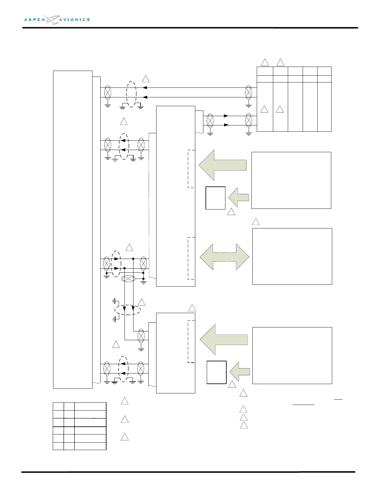
Figure 9.10 Pro ARINC 429 GPS & Dual Analog VLOC
with and w/o Autopilot Interface
ACU #1
P3
18
19
26
27
14
1
15
2
PFD 429 TX1A
PFD 429 TX1B
Autopilot - optional
See Figure:
9.16 for Bendix King
9.17 for S-TEC
9.18 for Century
9.19 for Cessna ARC
9.20 – 9.23A Flight Director
429 RX1B
429 RX1A
429 TX1B
429 TX1A
22
23
A
U
T
O
P
I
L
O
T
Analog VLOC #2
ARINC 429 GPS - optional
429 VLOC RX4A
429 VLOC RX4B
Analog VLOC #1
ACU #2
14
1
15
2
P3
429 RX1A
429 RX1B
Optional
Back-Up
Nav
Indicator
Optional
Back-Up
Nav
Indicator
V
L
O
C
#
2
V
L
O
C
#
1
429 TX1B
429 TX1A
Autopilot must be connected to ACU #1
See Figure 9.24, 9.25, 9.26 for Back-Up NAV
recommendations. If no GPS installed then One
backup NAV indicator is required.
1
2
3
GPS
400(W)
GPS
500(W)
GNC
300/XL
GPS
155XL
P4001
P5001
J101
J1
P3
4
5
16
17
GPS RX1A
GPS RX1B
429 TX2A
429 TX2B
16
15
16
33
32
46 46
47 47
48(50)
49(51)
15
49(51)
48(50)
33
32
4
Omit ACU #2 if using only 1 Analog Nav.
ID#1
Description
D
E
E
ID#2
NONE
NONE
D
GPS1, No NAV1,
No NAV2
GPS1,NAV1,
No NAV2
M
M
NONE
D
No GPS1, NAV1,
No NAV2
GPS1, NAV1, NAV2
No GPS1, NAV1,
NAV2
5
3
See Figure 9.15 for:
KX-155(A) &165(A)
KN-53
KX-170A/170B/175/175B
SL-30
See Figure 9.15 for:
KX-155(A) &165(A)
KN-53
KX-170A/170B/175/175B
SL-30
Use pins 48 & 49 or 50 & 51 not both.
6
3
2
2
4
4
Configure GPS-400/500 Out for “Low GAMA 429
Graphics w/Int”, IN for “Honeywell EFIS”, VNAV for
“Enable Labels”
1
1
1
1
Over shield or over braid required on this wire
bundle to comply with HIRF & Lightning. Extend
within back shell if possible. Ground at both ends.
7
6
5
Configuration Matrix
(see Section 10)
1
GPS
150/160
J1
16
15
-
-
Refer to manufacturers’ documentation to verify
the integration data and for information regarding
checkout procedures. This drawing, as it pertains
to the non-Aspen equipment, is for reference only.
 Loading...


