EFD1000 Installation Manual
DOCUMENT # A-01-126-00 PAGE 209-225 Revision H
© Copyright 2009 Aspen Avionics Inc.
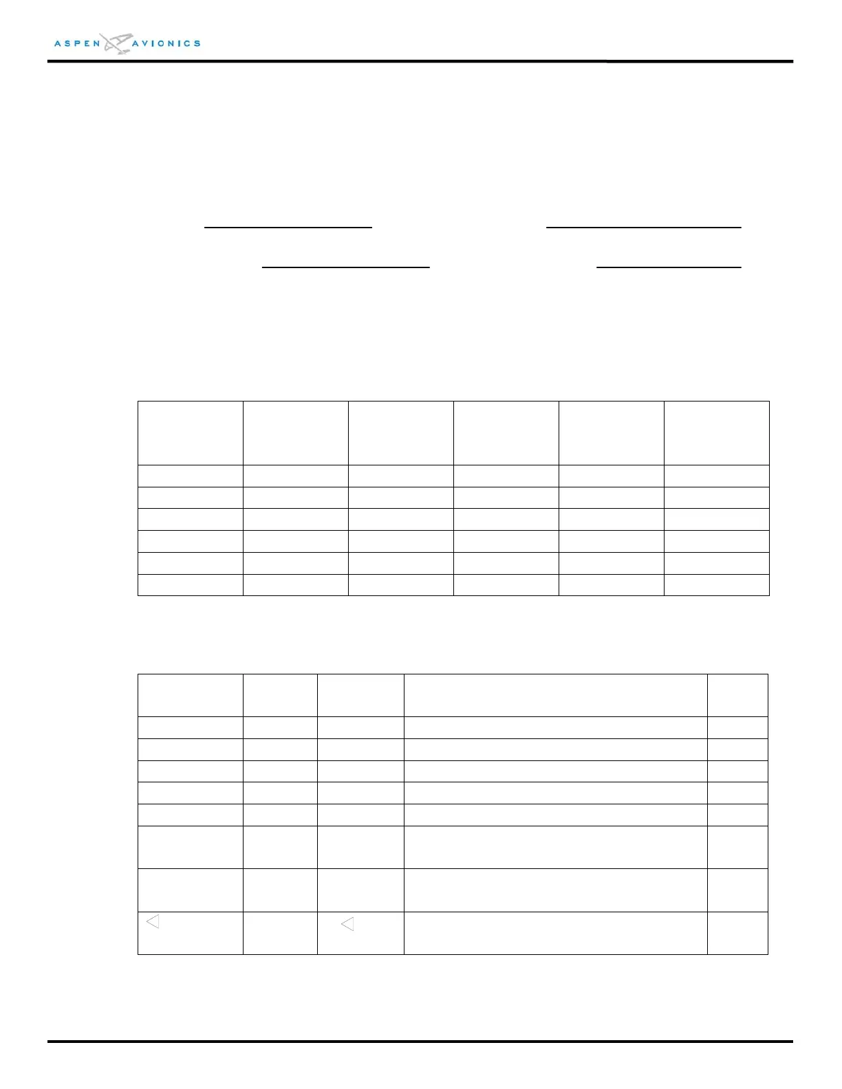
EFD1000 Installation Final Check Sheet
(page 1 of 4)
Aircraft Type: Date:
Aircraft Serial Number: Tail Number:
The following pages must be printed and used during checkout. The Section number refers to the
section in the manual where the test is performed. This form must be included in document
package to be included in aircraft maintenance records.
Complete by performing test of Section 10.5.4
Calibrated
Heading
Source
TOLERANCE Actual PFD
Heading
Calibrated
Heading
Source
TOLERANCE Actual PFD
Heading
30 +/- 4 210 +/- 4
60 +/- 4 240 +/- 4
90 +/- 4 270 +/- 4
120 +/- 4 300 +/- 4
150 +/- 4 330 +/- 4
180 +/- 4 360 +/- 4
Complete by performing test of Section 10.6.1
IAS Setting Band
Color
Band
Range
Description Pass
V
ne
= Red >V
ne
Red arc displayed at all speeds above V
ne
V
no
= Yellow V
no
- V
ne
Yellow arc extending from V
no
to V
ne
V
s
= Green V
s
- V
no
Green arc extending from V
s
to V
no
V
fe
= White V
so
- V
fe
White arc extending from V
so
to V
fe
V
so
=
V
yse
= Blue
Marker
= V
yse
Blue Marker at V
yse
V
mc
= Red
Marker
= V
mc
Red Marker at V
mc
=
Triangle
(White)
=
White triangle at initial flap extension
airspeed
NOTE: Single engine aircraft and aircraft with no flaps will not use all parameters above
 Loading...


