Chapter 1 – Installation of the instrument
UM-22100H-U User manual ATEQ D520 Page 18/122
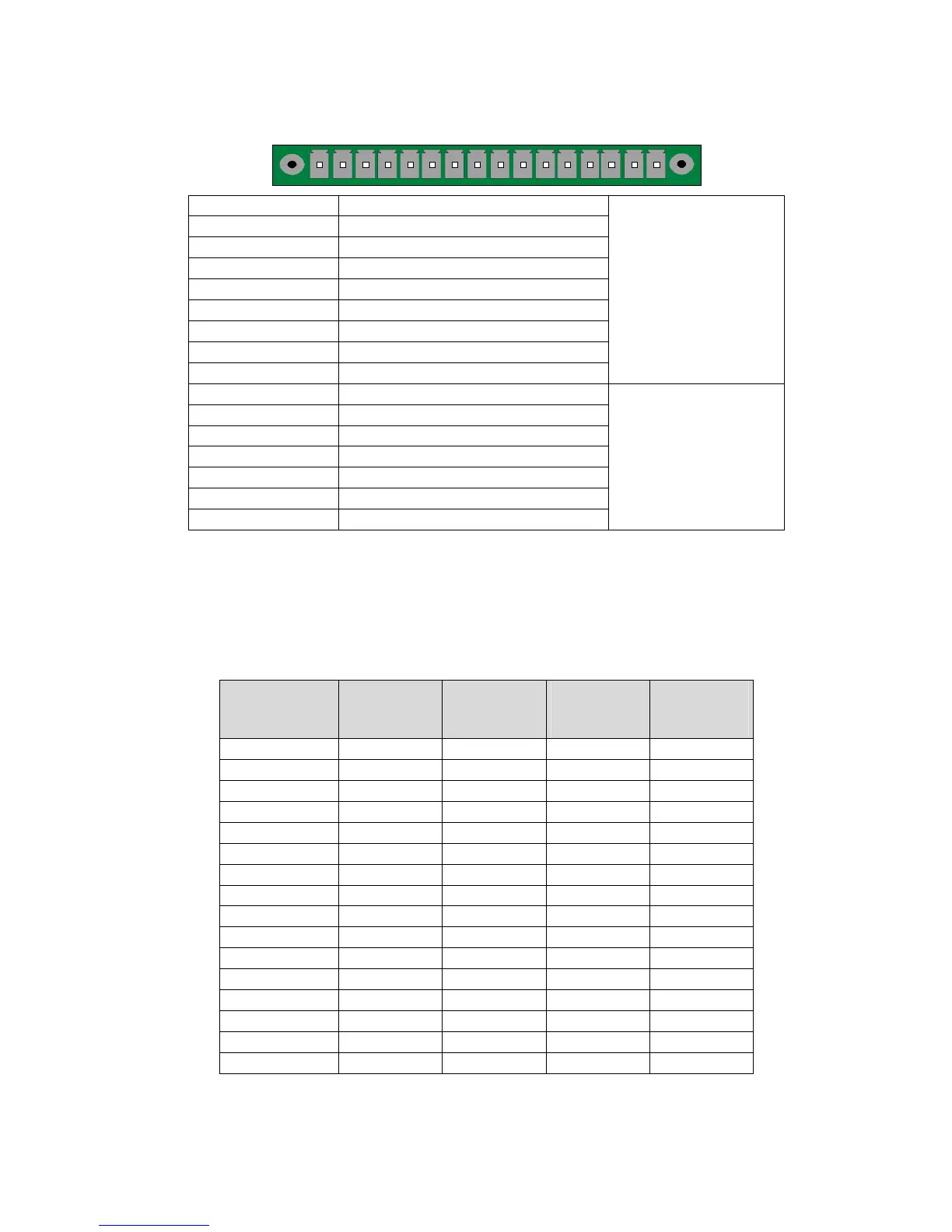
2.2.1. 3) J3 connector (Inputs/Outputs All or Nothing)
1 2 3 4 5 6 7 8 9 10111213141516
Pin 1 RESET input (input 1)
Pin 2 Common (+ 24 V)
Pin 3 START input (input 2)
Pin 4 Common (+ 24 V)
Pin 5 Input 3 (program selection)
Pin 6 Input 4 (program selection)
Pin 7 Input 5 (program selection)
Pin 8 Input 6 (program selection)
Pin 9 Input 7 (programmable input)
INPUTS
(Activation by
24 V DC)
Pin 10 Common floating outputs
Pin 11 Good part output
Pin 12 High bad part output
Pin 13 Low bad part output
Pin 14 Warning output
Pin 15 End of cycle output
Pin 16 0 V
DRY CONTACT
OUTPUTS
60V AC / DC Max
200mA Max
2.2.1. 4) Activation of a program on the J3 connector inputs
To activate a program on the J3 connector inputs, it is necessary to select pins 5 to 8
(one or more at a time). Binary weighting n + 1.
Combinations of the pins to be activated to select the programs
Program
number
Pin 5
(input 3)
Pin 6
(input 4)
Pin 7
(input 5)
Pin 8
(input 6)
1 0 0 0 0
2 1 0 0 0
3 0 1 0 0
4 1 1 0 0
5 0 0 1 0
6 1 0 1 0
7 0 1 1 0
8 1 1 1 0
9 0 0 0 1
10 1 0 0 1
11 0 1 0 1
12 1 1 0 1
13 0 0 1 1
14 1 0 1 1
15 0 1 1 1
16 1 1 1 1