Chapter 1 – Installation of the instrument
UM-22100H-U User manual ATEQ D520 Page 23/122
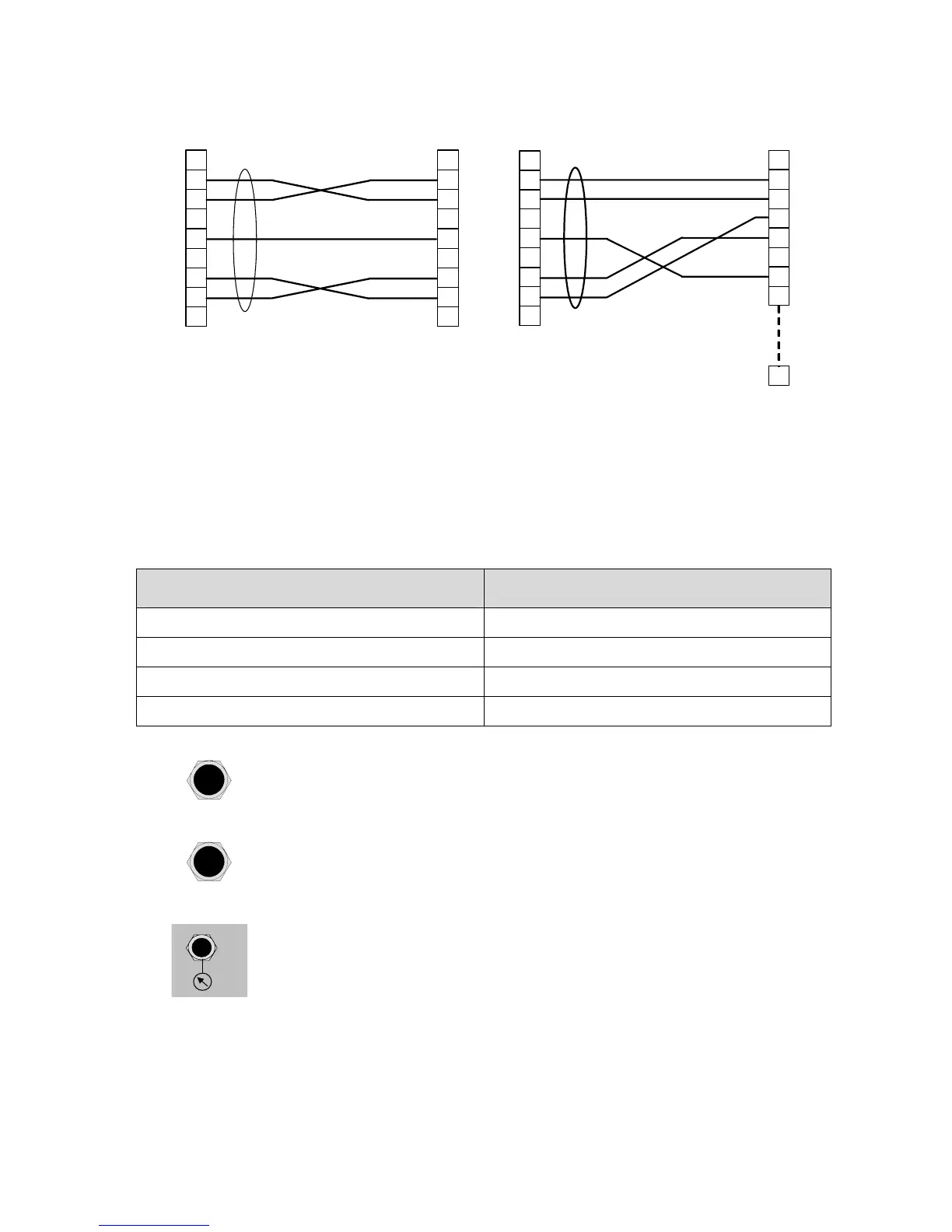
2.2.1. 12) Examples of RS232 cables
1
2
3
4
5
6
7
8
9
1
2
3
4
5
6
7
8
9
ATEQ
Operator
9 pin SubD
connector
9 pin SubD
connector
RX
TX
GND
RTS
CTS
RX
TX
GND
RTS
CTS
1
2
3
4
5
6
7
8
9
1
2
3
4
5
6
7
8
ATEQ
Operator
25
9 pin SubD
connector
25 pin SubD
connector
RX
TX
GND
RTS
CTS
RX
TX
GND
RTS
CTS
2.2.2. Pneumatic connectors
For the ATEQ D520, the automatic connectors can be installed on the front panel or on
the rear panel depending on the option chosen.
These pneumatic outputs can take on different functionalities depending on the
configuration requested following the purchase of the instrument (stamping, cut off,
dump, second test output, etc.).
"Automatic connector A" output "Automatic connector B" output
Automatic connector A Automatic connector B
Automatic connector A Stamping
Automatic connector A Cut off
Stamping External dump
2.2.2. 1) Automatic connector A
Allows the pneumatic management of a sealing jig.
2.2.2. 2) Automatic connector B
Allows the pneumatic management of a second sealing jig.
2.2.2. 3) Take pressure socket (option)
P
This optional connector allows to plug the absolute pressure sensor
the nearest as possible to the part to be controlled. Connector
dimensions: 2.7/4 tube.