Chapter 1 – Installation of the instrument
UM-22100H-U User manual ATEQ D520 Page 22/122
2.2.1. 7) J4 connector
Allows the connection of the power supply.
The instrument can be powered directly through the relay
board J3 connector on one of the 24 V DC pins.
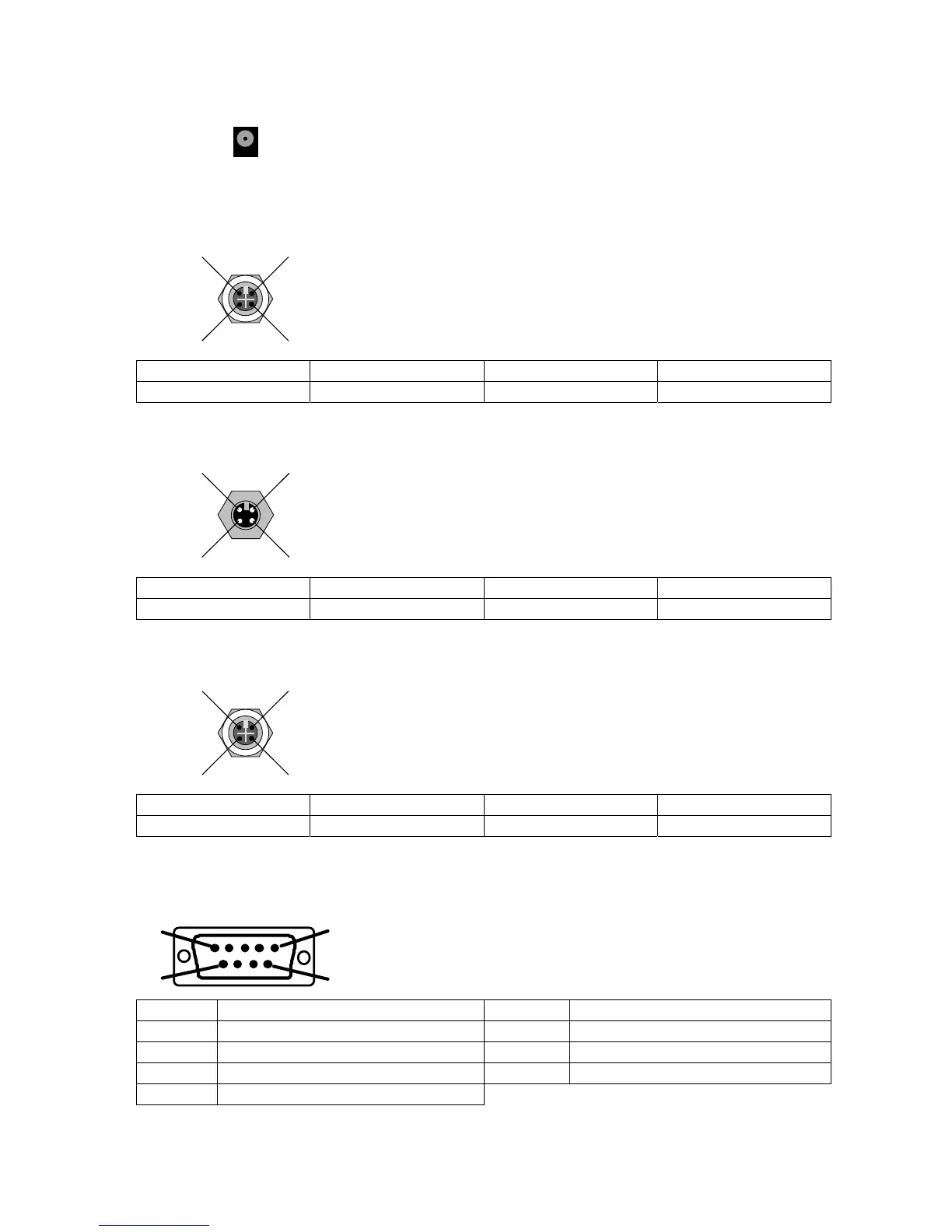
2.2.1. 8) J5 remote control connector (RS232)
2
1
4
3
Allows the connection of an intelligent remote control.
(Female Lumberg type connector). Optional.
PIN 1 Network (TXD) PIN 3 Network (RXD)
PIN 2 Power + 24V PIN 4 Ground 0V
2.2.1. 9) J6 input connector (RS485)
2 1
4
3
ATEQ only network.
Allows the connection to other ATEQ instruments. (Male
Lumberg type connector).
PIN 1 Network (D+) PIN 3 Network (D-)
PIN 2 Power + 24 V PIN 4 Ground 0V
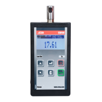
2.2.1. 10) J7 output connector (RS485)
2
1
4
3
ATEQ only network.
Allows the connection to other ATEQ instruments. (Female
Lumberg type connector).
PIN 1 Network (D+) PIN 3 Network (D-)
PIN 2 Power +24V PIN 4 Ground 0V
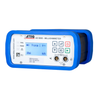
2.2.1. 11) J8 connector (RS232)
1
5
9
6
Allows the connection of a printer, a bar code reader, a PC,
a memory module.
PIN 1 Not connected PIN 6 + 5 V DC 200 mA max
PIN 2 RXD Reception of the data PIN 7 RTS request to send
PIN 3 TXD Sending of the data PIN 8 CTS clear to send
PIN 4 Not connected PIN 9 Not connected
PIN 5 Ground