Attaching the hydraulic
attachment to the carrier
Mechanical mounting aspects
You need an assistant to attach the hydraulic
attachment to the carrier.
◆
Agree on hand signals with your assistant, to
enable him to help you placing the carrier in the
proper position to attach the hydraulic
attachment.
WARNING Injury by impacts
A sudden movement of the carrier may cause your
assistant to be hit and injured by the boom or the
hydraulic attachment.
►
Only move the boom very slowly and in a
controlled manner while an assistant is within
the danger zone.
►
Always keep sight of your assistant.
WARNING Hands and fingers being cut off
or hurt
Bores and surfaces can act like a pair of scissors
and cut off or hurt parts of your body.
►
Never use your fingers to check bores or fitting
surfaces.
NOTICE Adapter plate can come loose
The adapter plate can come loose if the fastening
screws are not designed for local high loads.
►
Only use the Allen screws of strength category
8.8 and the pairs of lock washers included in
the delivery to attach the adapter plate or the
base plate.
◆
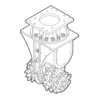
Place the transverse drum cutter on the
assembly stand within the range of the carrier.
◆
Apply Anti-Seize to the Allen screw threads (A)
before inserting them.
The contact faces of the screw head and the
lock washers (B) must not be lubricated.
◆
Align the adapter plate (C) with the transverse
drum cutter as shown.
◆
Fit a pair of lock washers (B) onto every screw.
◆
Tighten the Allen screws (A) with an Allen key.
◆
Tighten the Allen screws (A) with the required
tightening torque.
Type Key size Tightening torque
DC 200 24/27 mm
(0.95/1.06 in.)
170 Nm (125 ft lbs)
DC 400 24/27 mm
(0.95/1.06 in.)
170 Nm (125 ft lbs)
DC 600 17 mm (0.67 in.) 390 Nm (288 ft lbs)
DC 1000 17 mm (0.67 in.) 390 Nm (288 ft lbs)
DC 1200 22 mm (0.89 in.) 1500 Nm (1106 ft lbs)
DC 2000 22 mm (0.89 in.) 1500 Nm (1106 ft lbs)
DC 2100 22 mm (0.89 in.) 1500 Nm (1106 ft lbs)
DC 2900 22 mm (0.89 in.) 1500 Nm (1106 ft lbs)
◆
Lower the stick of the carrier into the holder
provided on the adapter plate.
◆
Let your assistant instruct you until the bores in
the adapter plate (C) and in the stick (D) are
properly aligned.
◆
Install the stick bolt (E) and lock it.
Safety and operating instructions DC 200, 400, 600, 1000, 1200, 2000, 2100, 2900
26 © Construction Tools GmbH | 3390 5192 01 | 2016-12-01
Original instructions
 Loading...