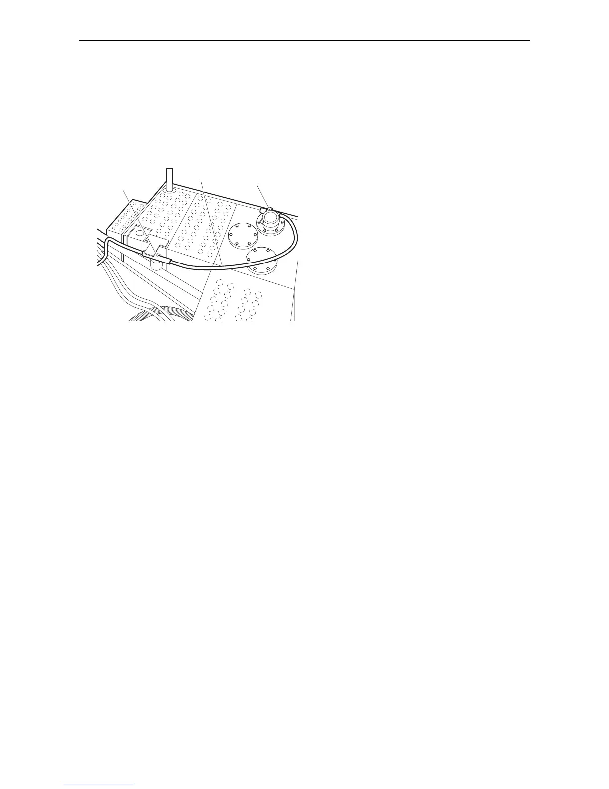
Follow the safety and operating instructions of
the carrier when connecting the leakage oil line
to the hydraulic oil tank.
◆
Attach the leakage oil line to the pre-installed
connection on the hydraulic oil tank and tighten
with the required tightening torque.
◆
Install the leakage oil filter at an appropriate
location on the carrier.
Making the hydraulic connections
NOTICE Faulty hydraulic installation
The carrier must have a suitable hydraulic
installation to operate the hydraulic attachment.
Improperly installed lines and incorrectly rated
sizes may cause the oil to heat up and the
hydraulic attachment to be damaged.
►
Only use hydraulic lines of the rated sizes as
instructed (see chapter Technical
Specifications).
►
Check the rated size of the hydraulic lines on
existing hydraulic installations! All supply and
return lines for the hydraulic oil must have a
sufficient inside diameter and wall thickness.
►
Route all hydraulic hoses in a torsion-free
manner.
◆
Switch off the carrier.
◆
Depressurise the hydraulic system according to
the manufacturer's safety and operating
instructions for the carrier.
◆
Close all shut-off valves in the installation at the
boom, if no quick couplings are used.
NOTICE
Damage to hydraulic parts
Polluted hydraulic lines and connections may
enable sand, fragments of material and dirt to
penetrate the hydraulic attachment and damage
the hydraulic parts.
►
Clean the hydraulic lines and connections prior
to connecting the hydraulic lines.
◆
Have dirty hydraulic lines rinsed through by a
specialist company.
◆
Clean dirty hydraulic line connections with a
suitable grease-dissolving universal cleaner.
◆
Observe the cleaner manufacturer's information
on safety and use.
NOTICE Property damage due to unauthorised
removal of the check valve
Removing the check valve from the tank line of
hydraulic hammer systems leads to destruction of
the hydraulic motor of the transverse drum cutter.
►
Never remove the check valve from the tank
line of hydraulic hammer systems.
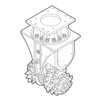
The transverse drum cutter is supplied with 3
hydraulic hoses, already installed by the
manufacturer:
•
Pressure line to the transverse drum cutter
•
Tank line with check valve to the carrier
•
Leakage oil line to the carrier
Note: Installation of a hydraulic circuit suitable for
operating a transverse drum cutter on the carrier is
the responsibility of the operator. The actions and
safety requirements pertinent to this can be found
in the carrier's operating manual.
For operation of the transverse drum cutter,
required adjustments (pressure and hydraulic flow)
on the carrier are the responsibility of the operator.
•
Consult, for installation to a carrier with
hydraulic hammer system, installation plan 1
(see chapter Hydraulic installation version 1 for
hydraulic hammer).
•
Consult, for installation to a carrier with
hydraulic shear system, installation plan 2 (see
chapter Hydraulic installation version 2 for
hydraulic shear systems).
Note: If it is necessary to remove the check valve,
e.g. when connecting to a hydraulic shear system
for backwards and forwards rotation, it is
necessary to guarantee that the pressure in the
tank line is at least 5 bar higher than that in the
leakage oil line at all times. This pressure
differential must be measured, documented and
communicated to Atlas Copco to prevent the
warranty on the hydraulic motor becoming null and
void.
Safety and operating instructions DC 200, 400, 600, 1000, 1200, 2000, 2100, 2900
28 © Construction Tools GmbH | 3390 5192 01 | 2016-12-01
Original instructions
 Loading...