14.4.3. Motor running time-torque (histogram)
Conditions
MWG position transmitter in actuator
Characteristics
The torque scale is divided into the following segments for both directions
(OPEN/CLOSE):
from 0 – 30 %
from 30 – 110 % (8 segments with a width of 10 % each)
more than 110 %
During each operation, the counter of the segment corresponding to the currently
required torque will be incremented.The result is shown in a bar chart.The histogram
is cyclically saved once a minute, in case a change has occurred.
Application
The motor running time-torque histogram indicates the actuator load during service
life.
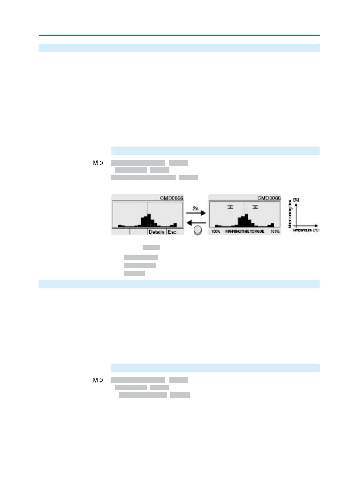
Display motor running time-torque
Asset Management M1231
Histograms M0712
Motor TunTime-Torque M0830
Figure 58: Example of motor running time-torque histogram
The following further information is saved with the histogram (can be requested via
push button Details)
●
Starting date:.
●
Saving date:.
●
Scaling:.
14.4.4. Frequency-acceleration (histogram)
Conditions
MWG position transmitter in actuator
Characteristics
The histogram shows the distribution of peak values of the total acceleration. The
peak values of a sampling interval preset in the factory are recorded and summed
up in ten different acceleration ranges with 0.2 g range each (0 – 0.2 g, ..., 3.8 – 4.0
g).
Application
The histogram indicates how often the actuator controls were in which range of the
total acceleration, i.e.the frequency and the impact of the oscillation (vibration of the
pipeline, for example) acting upon the actuator controls Impermissibly high or
persisting oscillations might destroy components of the actuator or the actuator
controls.
Display acceleration-frequency
Asset Management M1231
Histograms M0712
Frequency-accel. M1965
117
Actuator controls
ACV 01.2/ACVExC 01.2 Plant Asset Management

 Loading...


