For detailed information on these signals, refer to <Fault signals and warnings>
chapter.
Configure status signals
Required user level: Specialist (4) or higher.
Device configuration M0053
Config. of signals M0860
Failure (configurable) M0879
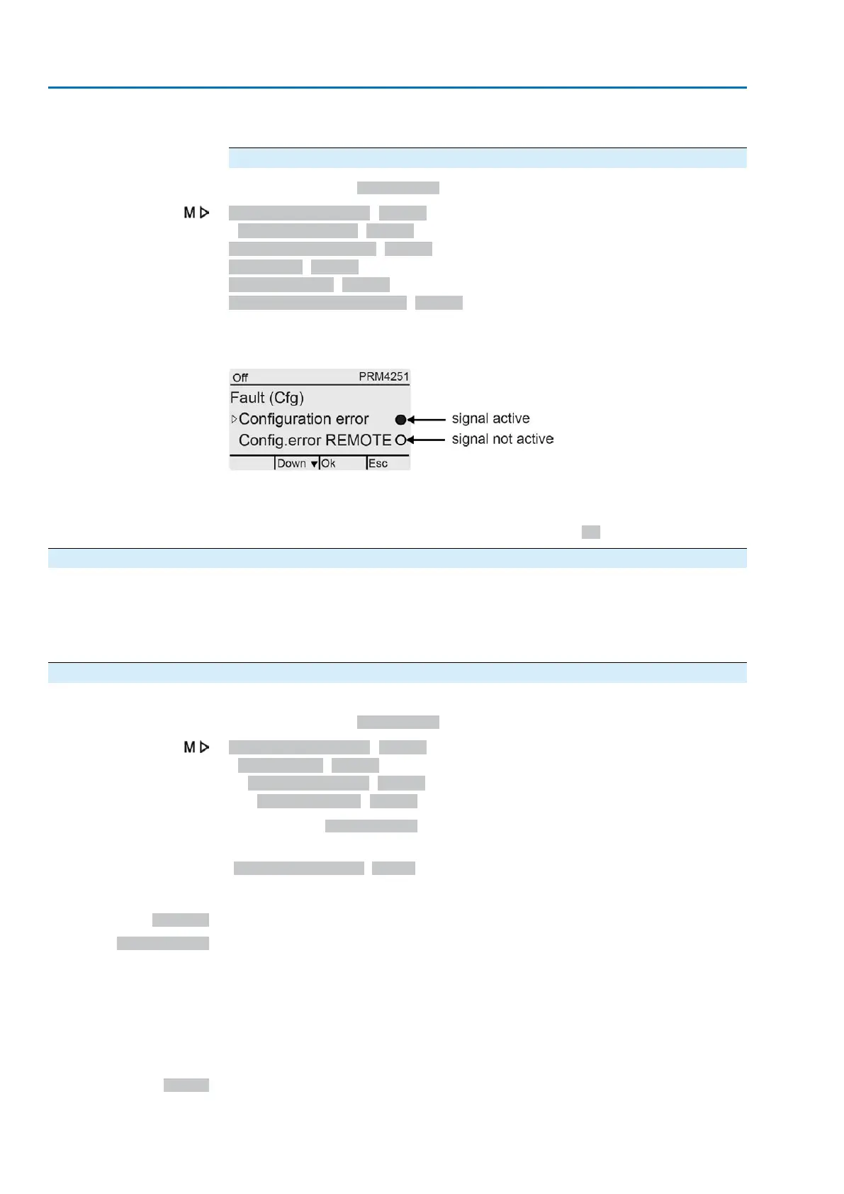
Fault (Cfg) M0880
Warnings (Cfg) M0881
Not ready REMOTE (Cfg) M0882
A dot in the display indicated whether the signal is active or not.
Figure 32: Example
Black dot (●): Signal active
White dot (○): Signal not active
Activation/deactivation is switched on/off by push button Ok.
5.3. Analogue signals (analogue outputs)
Conditions
The actuator is equipped with a position transmitter.
Characteristics
Depending on the actuator equipment, different signals, such as travel, torque or
output speed can be recorded and issued as continuous values, e.g. 4 to 20 mA.
Actuator controls are equipped with up to two analogue outputs, AOUT1 and AOUT2.
5.3.1. Assignment of analogue output 1
Designation in the wiring diagram: AOUT 1.
Required user level: Specialist (4).
Device configuration M0053
I/O interface M0139
Analogue outputs M0335
Signal AOUT 1 M0131
Default value: Actual position
Information
The signal range of the output (e.g. 0/4 – 20 mA) is set via a separate parameter
(Signal range AOUT1 M0129).
Setting values:
Not used
Analogue output 1 is not assigned.
Actual position
Position feedback of the valve position (actual position value E2)
Condition: Position transmitter installed in the actuator.
An adjustment to the end positions or the defined travel is not required. An automatic
adjustment is done via the end positions (LSC (WSR) and LSO (WOEL)).
For torque seating, the end positions OPEN and CLOSED of the limit switching
should be set as close as possible to the end positions of the valve to minimise the
deviation of the feedback.
Torque
Torque feedback E6
Condition: MWG position transmitter in actuator.
28
Actuator controls
Signals (output signals) ACV 01.2/ACVExC 01.2

 Loading...


