9.2.5. Speed for safety operation: set
The speed during safety operation may be set individually for both direction
(OPEN/CLOSE).
Required user level: Specialist (4) or higher.
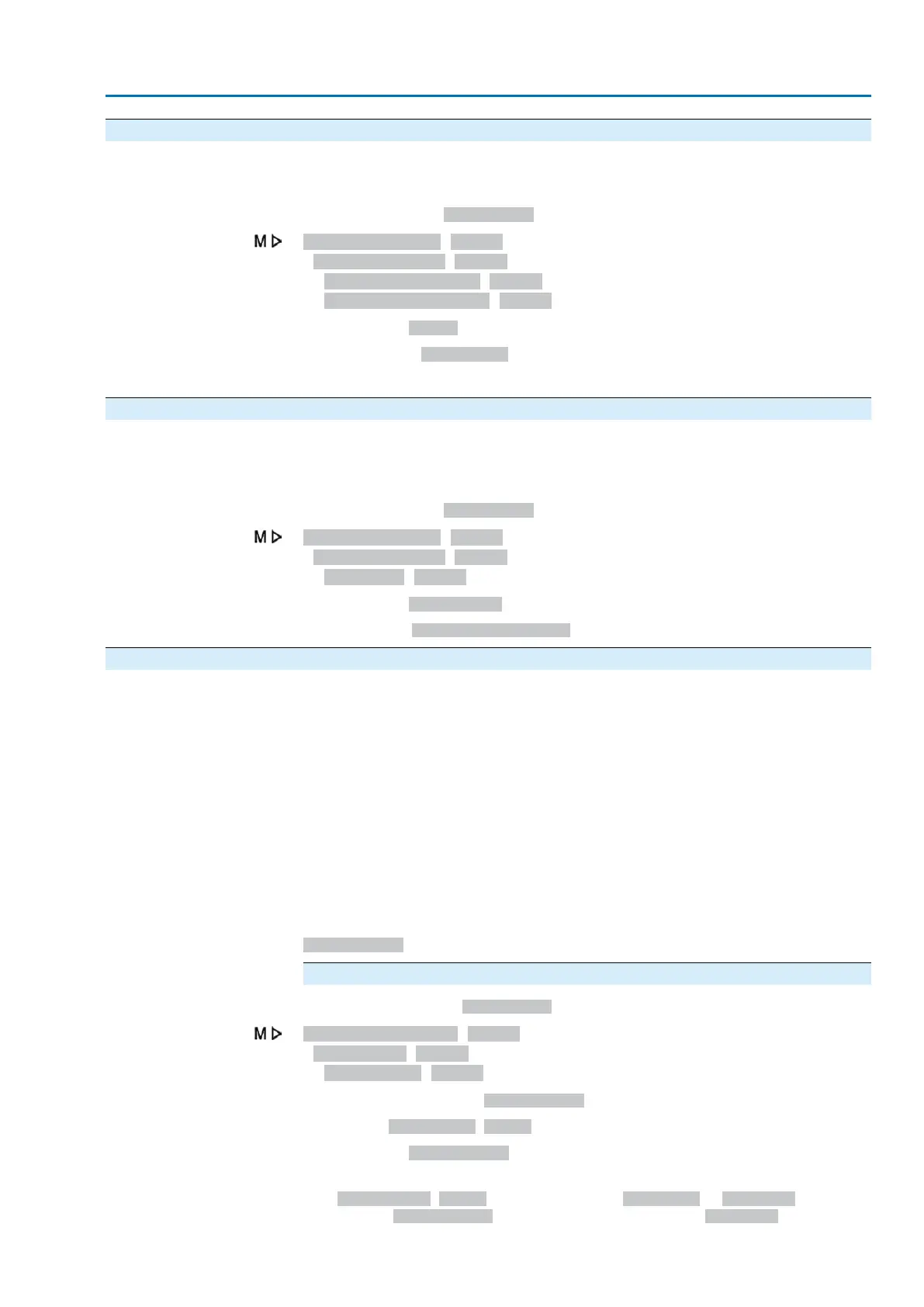
Customer settings M0041
Failure behaviour M0378
Failure speed OPEN M1935
Failure speed CLOSE M2042
Default value: 45 rpm
Setting ranges: 6 ... 240 rpm
The adjustable speed range is indicated on the actuator name plate.
9.2.6. Delay time: set
A failure operation is only performed once the delay time has expired.This prevents
a short-term loss of signal, which does not have an effect on the process, from directly
starting a failure operation
Required user level: Specialist (4) or higher.
Customer settings M0041
Failure behaviour M0378
Delay time M0386
Default value: 00:03.0 min:s (3 seconds)
Setting range: 0.0 ... 30:00.00.0 min:s (30 minutes)
9.3. EMERGENCY behaviour
Application
The EMERGENCY behaviour can be used to determine the actuator behaviour in
an emergency.
Characteristics
●
The function <EMERGENCY behaviour> is initiated by the EMERGENCY signal.
●
The actuator performs a defined EMERGENCY operation. For example, the
actuator moves to a predefined EMERGENCY position (i.e. end position OPEN
or end position CLOSED).
●
As long as the EMERGENCY signal is present, the actuator does not respond
to any other operation commands (EMERGENCY signal has top priority).
●
After initiating the EMERGENCY behaviour, binary operation commands (via
digital inputs) may have to be sent again.
●
Analogue operation commands (e.g. 0/4 – 20 mA) are immediately executed
again.
Condition
For the function <EMERGENCY behaviour>, a digital input for the signal
EMERGENCY has to be available and configured.
Configuration of digital input
Required access level: Specialist (4).
Device configuration M0053
I/O interface M0139
Digital inputs M0116
Example
Use input DIN 4 for signal EMERGENCY:
Parameter: Signal DIN 4 M0118
Setting value: EMERGENCY (wiring diagram designation: EMERGENCY)
Information
The logic for the digital inputs may be inverted. Depending on the parameter setting
(e.g. Coding DIN 4 M0126), the input is either High active or Low active. For safety
reasons, the EMERGENCY signal input is generally set to Low active.
75
Actuator controls
ACV 01.2/ACVExC 01.2 Failure functions

 Loading...


