The simulation is activated and deactivated by push button Ok.
A loop on the display indicates that the simulation is active.
13.11.2. Interface signals
By simulating the interface signals, the signal behaviour of the AUMATIC to the DCS
can be tested, for example, without having to connect the actuator.
Required access level: Specialist (4) or higher.
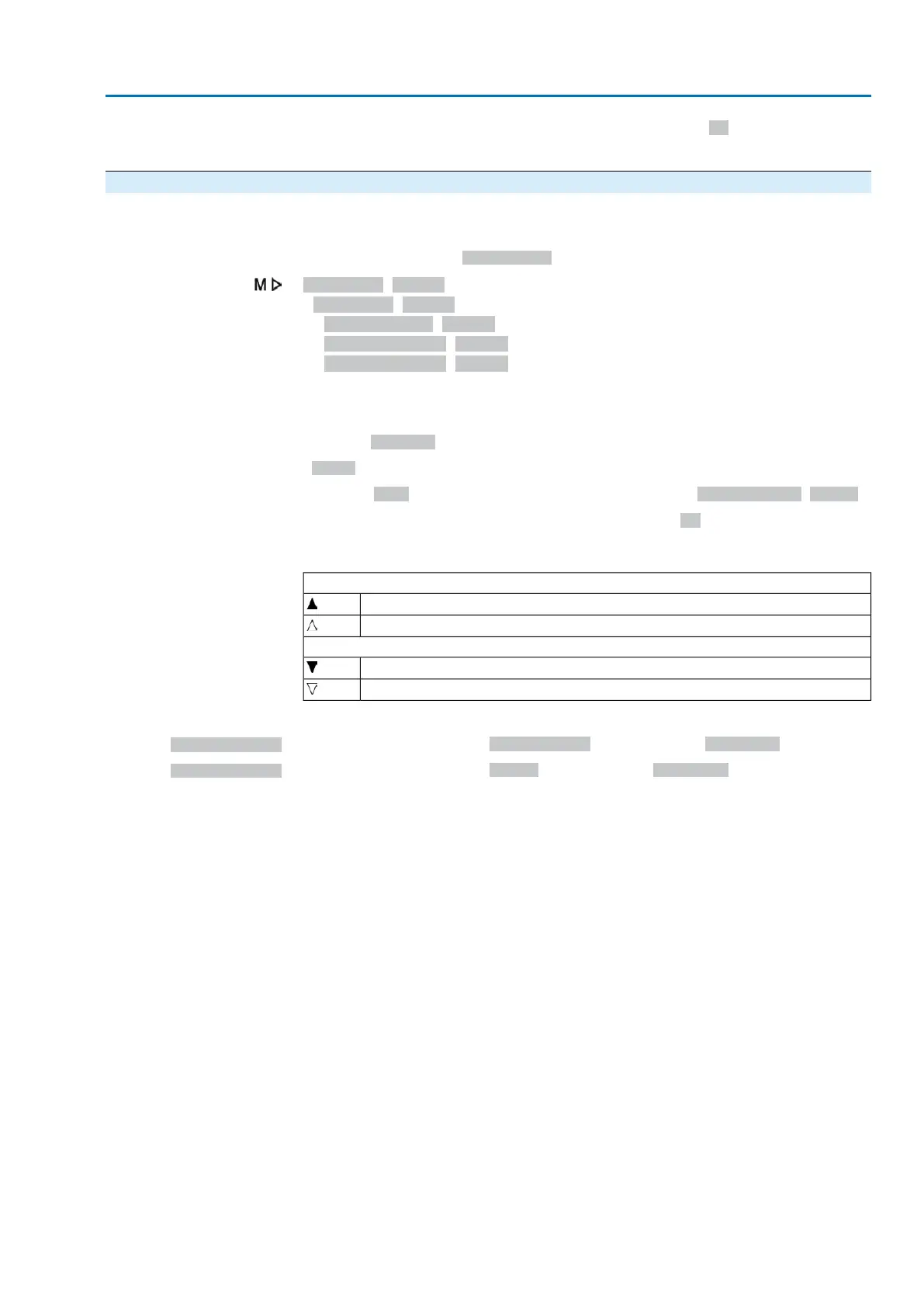
Diagnostic M0022
Simulation M0023
Signals DOUT M0025
Signals AOUT 1 M0413
Signals AOUT 2 M0585
Signals for simulating digital outputs:
Only the assigned outputs are displayed.
Numbers 1, 2, 3, ... indicate the digital output.
Example:
1Fault
Indication Fault is assigned to digital output 1 (parameter Signal DOUT 1 M0109).
Simulation is activated and deactivated by push button Ok.
Triangles indicate the activation:
Triangle pointing in upward direction: Output is coded high active.
High active (voltage is present, e.g. + 24 V DC)
High active (voltage is not present)
Triangle pointing in downward direction: Output is coded low active.
Low active (voltage is not present)
Low active (voltage is present, e.g. + 24 V DC)
Signals for simulating analogue outputs:
Signals AOUT 1
Simulation of output signal Actual position, setting range: 0 ... 20 mA
Signals AOUT 2
Simulation of output signal Torque, setting range: 0 ... 20 mA
109
Actuator controls
ACV 01.2/ACVExC 01.2 Diagnostics

 Loading...


