Parameter: Signal DIN 5 M0122 = Speed int. sel. bit 0
Parameter: Signal DIN 6 M0123 = Speed int. sel. bit 1
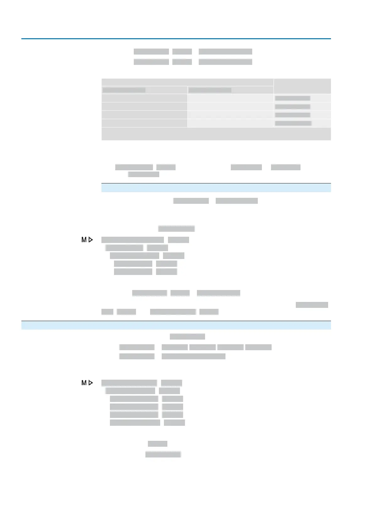
Table 8:
Output speed
1)
Input signals (DIN) for external speed selection
Speed int. sel. bit 1Speed int. sel. bit 0
Speed internal1
00
Speed internal2
10
Speed internal3
01
Speed internal 4
11
0 = low level (0 V DC or input open)
1 = high level (standard: +24 V DC)
Speed value for coding both digital inputs with “high active”1)
Information
The logic for the digital inputs may be inverted. Depending on the parameter setting
(e.g. Coding DIN 6 M0128), the input is either High active or Low active. Default
setting is High active.
Configuration of analogue input for speed
For setting of parameter Sp. source... = Analogue input.
An analogue input (AIN 1 or AIN 2) has to be configured as described to be able to
use an external (analogue) speed setpoint.
Required user level: Specialist (4).
Device configuration M0053
I/O interface M0139
Analogue inputs M0389
Signal AIN 1 M0135
Signal AIN 2 M0138
Example
Use analogue input AIN 1 for speed setpoint:
Parameter Signal AIN 1 M0135 = Interface speed
Information
The speed range for the analogue input is determined via parameters Speed rem.
min. M1936 and Speed rem. max M1937.
8.1.2. Speed for constant (internal) speed setpoint: set
For setting of parameter Sp. source... (internal speed setpoint)
●
Sp. source... = Internal 1/Internal 2/Internal 3/Internal 4
●
Sp. source... = 2 DigIn: "Internal (1-4)"
If the actuator is controlled via an external speed source, the internal speed values
described here will not have an impact on the operation behaviour.
Customer settings M0041
Speed functions M1699
Speed internal1 M1930
Speed internal2 M1931
Speed internal3 M1932
Speed internal 4 M1933
Default values:
Default values: 45 rpm
Setting range: 6 ... 240 rpm
The adjustable speed range is indicated on the actuator name plate.
46
Actuator controls
Application functions ACV 01.2/ACVExC 01.2

 Loading...


