5. Signals (output signals)
5.1. Status signals via output contacts (digital outputs)
Characteristics
Output contacts are used to send status signals (e.g. reaching the end positions,
selector switch position, faults...) as binary signals to the control room.
Status signals only have two states: active or inactive. Active means that the
conditions for the signal are fulfilled.
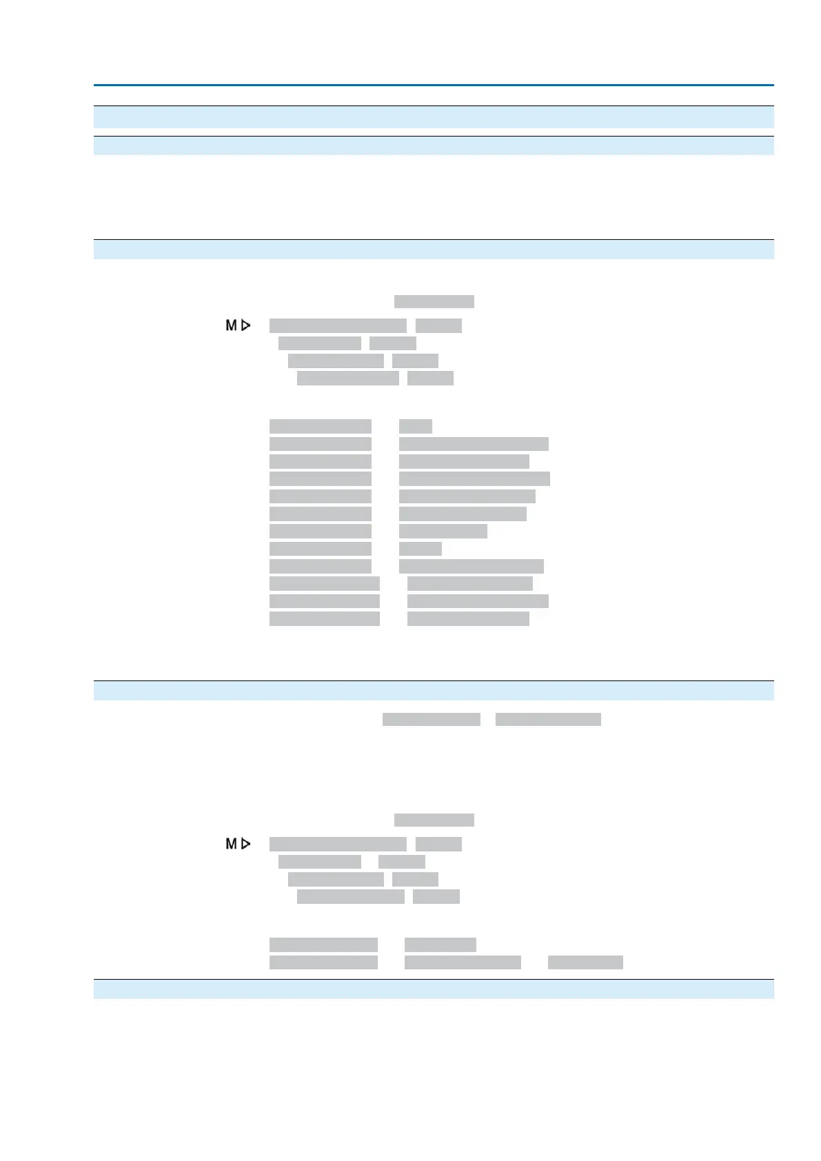
5.1.1. Assignment of outputs
The output contacts (outputs DOUT 1 – 12) can be assigned to various signals.
Required user level: Specialist (4) or higher.
Device configuration M0053
I/O interface M0139
Digital outputs M0110
Signal DOUT 1 M0109
Default values:
Signal DOUT 1 = Fault
Signal DOUT 2 = End position CLOSED
Signal DOUT 3 = End position OPEN
Signal DOUT 4 = Selector sw. REMOTE
Signal DOUT 5 = Torque fault CLOSE
Signal DOUT 6 = Torque fault OPEN
Signal DOUT 7 = Thermal fault
Signal DOUT 8 = OPEN
Signal DOUT 9 = Limit switch CLOSED
Signal DOUT 10 = Limit switch OPEN
Signal DOUT 11 = Torque sw. CLOSED
Signal DOUT 12 = Torque sw. OPEN
Further setting values:
Refer to <Appendix>/<Selection overview for output contacts and indication lights>
5.1.2. Coding the outputs
The output signalsCoding DOUT 1 – Coding DOUT 12 can be set either to high
active or low active.
●
High active = output contact closed = signal active
●
Low active = output contact open = signal active
Signal active means that the conditions for the signal are fulfilled.
Required user level: Specialist (4) or higher.
Device configuration M0053
I/O interface M0139
Digital outputs M0110
Coding DOUT 1 M0102
Default values:
Coding DOUT 1 = Low active
Coding DOUT 2 – Coding DOUT 12 = High active
5.2. Configurable status signals
The status signals described here are collective signals of various other signals. For
configuration, the contained signals can be selected from a list and activated ( ) or
deactivated ( ) individually.
The status signals can either be assigned to a digital output (output contact) or to
an indication light (LED).
27
Actuator controls
ACV 01.2/ACVExC 01.2 Signals (output signals)

 Loading...


