The following examples show how to generate the Modbus address and data type for hosts
which require this format.
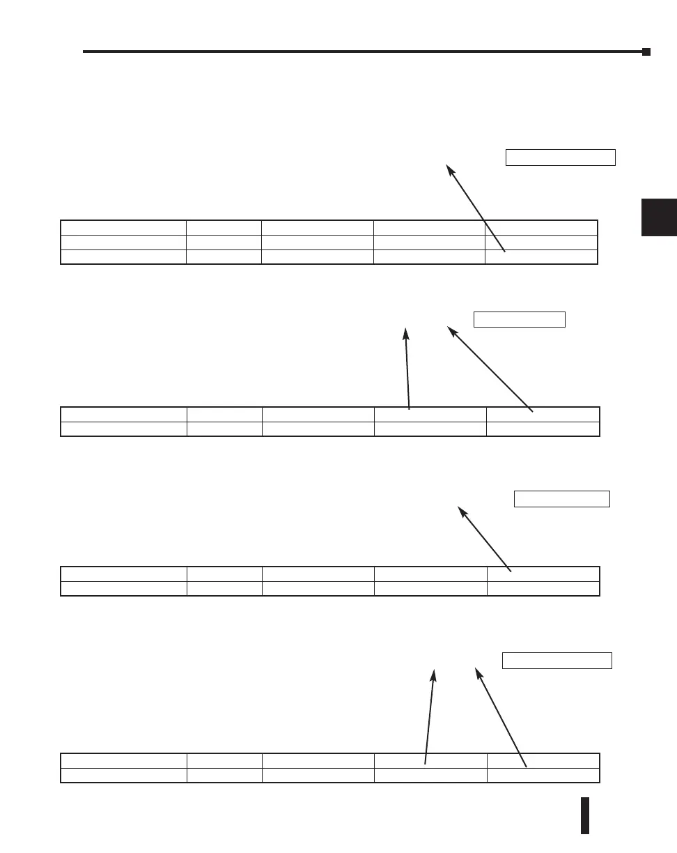
Example 1: V2100
Find the Modbus address for User
V location V2100.
1. Find V memory in the table.
2. Convert V2100 into decimal (1089).
3. Use the Modbus data type from the table.
Example 2: Y20
Find the Modbus address for
output Y20.
1. Find Y outputs in the table.
2. Convert Y20 into decimal
(16).
3. Add the starting address for the range (2049).
4.
Use
the
Modbus data type from the table.
Example 3: T10 Current Value
Find the Modbus address to obtain the
current value from Timer T10.
1. Find Timer Current Values in the table.
2. Convert T10 into decimal (8).
3. Use the Modbus data type from the table.
Example 4: C54
Find the Modbus address for
Control Relay C54.
1. Find Control Relays in the table.
2. Convert C54 into decimal (44).
3. Add the starting address for the range (3073).
4. Use the Modbus data type from the table.
DL205 User Manual, 4th Edition, Rev. B
4–37
Chapter 4: System Design and Configuration
1
2
3
4
5
6
7
8
9
10
11
12
13
14
A
B
C
D
Outputs (Y) 320 Y0 – Y477 2049 – 2367 Coil
Control Relays (CR) 256 C0 – C377 3072 - 3551 Coil
Timer Current Values (V) 128 V0 – V177 0 – 128 Input Register
Counter Current Values (V) 128 V1000 – V1177 512 – 639 Input Register
Outputs (Y) 320 Y0 – Y477 2048 - 2367 Coil
Control Relays (C) 256 C0 – C377 3073 – 3551 Coil
PLC Address (Dec.) + Data Type
V2100 = 1088 decimal
1088 + Hold. Reg. =
PLC Addr. (Dec) + Start Addr. + Data Type
Y20 = 16 decimal
16 + 2049 + Coil =
PLC Address (Dec.) + Data Type
T10 = 8 decimal
8 + Input Reg. =
PLC Addr. (Dec) + Start Addr. +Data Type
C54 = 44 decimal
44 + 3073 + Coil =
Coil 2065
Holding Reg. 1089
Input Reg. 9
Coil 3117
Timer Current Values (V) 128 V0 - V177 0 - 127 Input Register
Counter Current Values (V) 128 V1000 - V1177 512 - 639 Input Register
V Memory, user data (V) 1024 V2000 - -V3777 1024 - 2047 Holding Register

 Loading...

