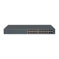
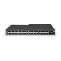
The ERS 3550 switch models comprise the following hardware features:
• RJ45 Console Port
• Status LEDs
• Base Unit Switch
• PoE+
• Stacking ports utilizing SFP running at 2.5Gbs. Stacking ports are configurable as 1Gbs SFP
uplink ports.
RJ45 Console Port
The standard ADS console port (DTE) is RJ-45 female connector (8-pin RJ-45). The following table
details the mandatory and optional pin assignment on the RJ-45 port.
Status LEDs
The System Status LEDs are located on the left side of the unit and include PWR, Status, UP,
Down, and Base. The following table defines the operation of the Status LEDs.
LED
State Definition
PWR Off The unit power is off.
Green (Solid) Normal operation.
Green (Blinking) The system is in reset.
Status Off System cannot work properly (like
temperature is too high).
Amber (Solid) Non-critical warning (the system
can still work)
Amber (Blinking) The system failed self-test
Green (Solid) Everything is OK
UP/Down Off No Stack-up or Stack-down
connection is detected.
Amber (Solid) A Stack-up or Stack-down cable is
detected, but adjacency has not
been completed.
Green (Solid) The unit has formed a neighbor
with an adjacent unit over the
Stack-up or Stack-down cables.
Table continues…
Introduction to ERS 3500 series switch models
July 2015 Getting Started with Avaya ERS 3500 Series 155
Comments on this document? infodev@avaya.com

 Loading...