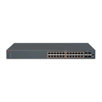
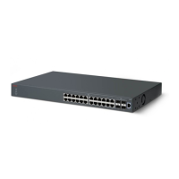
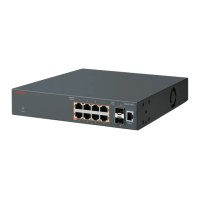
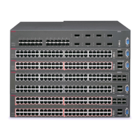
Figure 8: CFG mirror images in the stack after removing the BU (unit 1)
As shown in the previous figure:
• Unit 2 becomes the TEMP-BU.
• The CFG 1 mirror image (residing in unit 2) becomes INACTIVE.
• A second copy of the INACTIVE CFG 1 mirror image is created in unit 3.
• The TEMP-BU (unit 2) contains all CFG mirror images of the stack's NBUs.
• The CFG 2 mirror image is created in unit 3. Unit 3 becomes the next TEMP-BU in case the
current TEMP-BU is removed.
Note:
If you have a system of two units or stacks of 3 to 8 units that are in BOTH DIRECTIONS
configuration, the CFG of the Base Unit is not mirrored and the Base Unit is not ready for
replacement. The CFG for the Base Unit is always mirrored on the next Base Unit (i.e. the unit
that becomes the TEMP-BU when the Base Unit fails). In these specific stack configurations,
there is no next Base Unit — if the Base Unit fails, the remaining units become standalone.
Auto Unit Replacement
July 2015 Getting Started with Avaya ERS 3500 Series 33
Comments on this document? infodev@avaya.com

 Loading...


