200
Installing the S8700 IP Connect
May 2002
Test the C-LAN Connectivity
1 To test the external IP connections, ping the C-LAN circuit pack and ping a known
computer connected to your network. If everything is configured correctly, the Result
column on the Ping Results screen reads PASS. If it reads ABORT, verify the IP-address
information and check the connectivity, including the cabling.
2 To ping the C-LAN server, type ping ip-address nnn.nnn.nnn.nnn board UUCSS and
press
Enter.
The variable nnn.nnn.nnn.nnn is the IP address of the TN799DP C-LAN circuit pack
and UUCSS is the cabinet, carrier, and slot of the TN799DP C-LAN circuit pack.
3 Type ping ip-address nnn.nnn.nnn.nnn board UUCSS and press Enter.
The variable nnn.nnn.nnn.nnn is the IP address of another computer beyond the gateway
and UUCSS is the cabinet, carrier, and slot of the TN799DP C-LAN circuit pack.
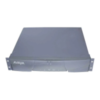
Test Stratum 3 Clock (if used—S8700
Multi-Connect only)
These procedures test the ability of the Stratum 3 clock to correctly provide timing and alarms
to the media server.
!
CAUTION:
The following procedures are destructive to DS1 data and should not be attempted while
DS1 facilities are active.
Check for Red LEDs
1 Turn on the Stratum 3 clock and wait 40-50 seconds to allow the system to complete the
on-board diagnostics before checking LEDs.
2 If there are any red LEDs, follow the procedures in ‘‘Stratum 3 Clock LED Indicators’’
on page 200.
Stratum 3 Clock LED Indicators
Card LED Label Procedure
PAI REF A Check that the CI circuit pack on the left is inserted properly.
Check wiring for DS1 in carrier A which connects the media
gateway to the CSU and the External Synchronization Clock at
the MDF through a Y-cable assembly. If all else fails to clear the
LED then replace the circuit pack.
PAI REF B Check that the CI circuit pack on the right is inserted properly.
Check wiring for DS1 in carrier B which connects the media
gateway to the CSU and the External Synchronization Clock at
the MDF through a Y-cable assembly. If all else fails to clear the
LED then replace the circuit pack.
PAI ST A Replace the ST3 card

 Loading...


