Installing a Meter with a Remote Transmitter and Fixed Transducers
• Locate the transmitter within the length of the transducer cables supplied or exchange the cable for one of proper length.
• See Figure 2 on page 6 for enclosure and mounting dimension details. Allow enough room for door swing, maintenance
and conduit entrances.
MPORTANTI
When routing wires to the transmitter, make sure the cables are not twisted, pinched or hanging loosely.
1. Install the xed transducers according to instructions in the transducer user manual.
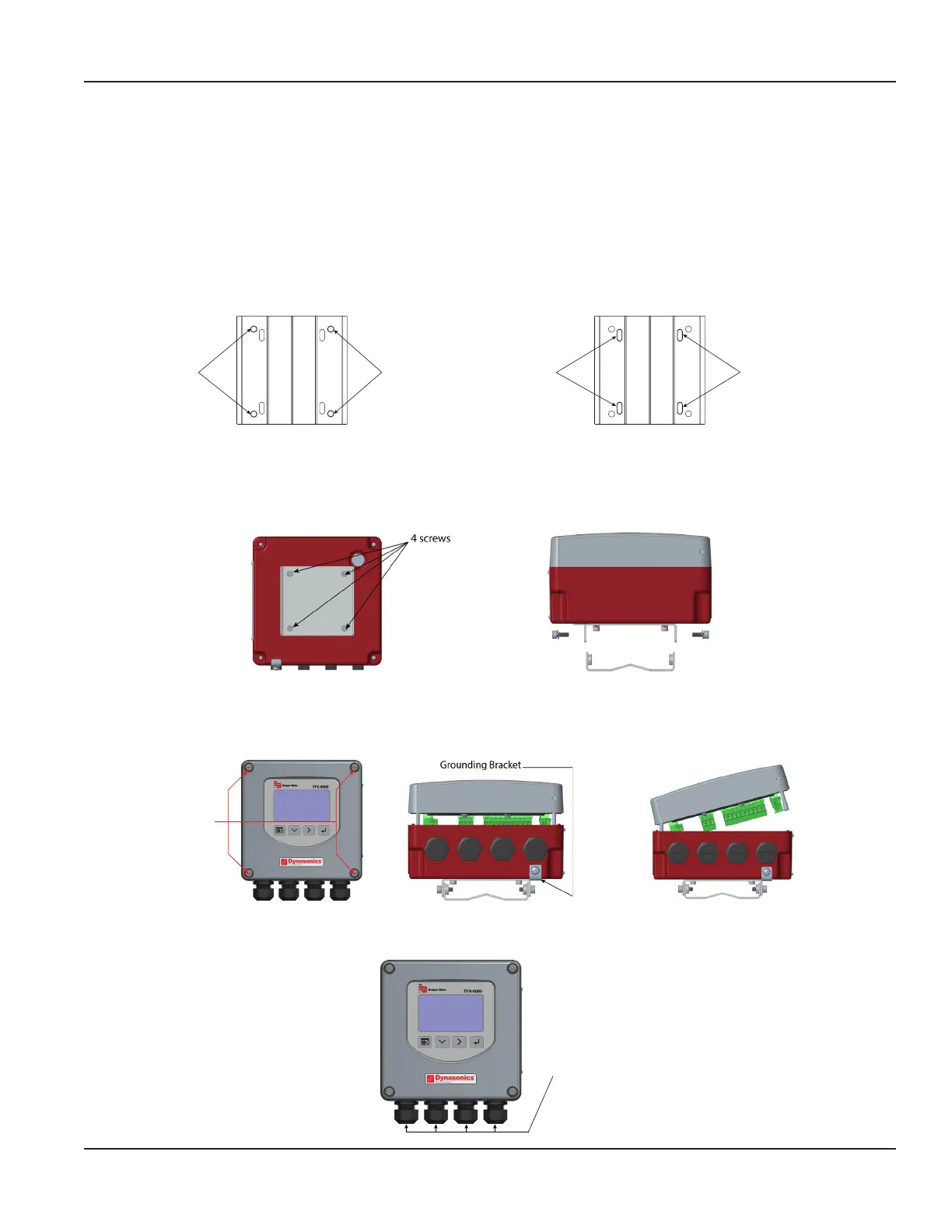
2. Attach the mounting bracket to a wall (with 4 customer-supplied #8 or M4 screws, see “Wall Mount Bracket” on page7
for dimensions) or to a pipe (with mounting straps).
Holes for
Screws for
Holes for
Screws for
Slots for
Straps for
Pipe Mounting
Slots for
Straps for
Pipe Mounting
Figure 5: Wall mount Figure 6: Pipe Mount
3. Align the transmitter's bracket with the mounted bracket. Use a 4 mm hex tool to secure the 4 provided screws from the
sides through the mating holes. See Figure 8.
4. If necessary, you can rotate the mounting bracket in 90° increments to accommodate the nal orientation of the
transmitter. From inside the enclosure, remove the 4 screws holding the bracket. Rotate the bracket and replace the
screws. See Figure 7.
Figure 7: Rotatable adapter plate Figure 8: Secure the bracket
5. Insert a wire for earth ground under the grounding bracket (see Figure 10) and screw it down tight.
6. Partially loosen the 2 enclosure captive screws on the left side of the transmitter cover. Completely loosen the 2 screws on
the right side. Grasp and lift the cover and open it to the left. The cover remains attached and the left screws act as a hinge.
Unscrew
Captive Screws
Figure 9: Captive cover screws Figure 10: Lift cover from base Figure 11: Open cover to the left
7. Use conduit holes where cables enter the enclosure from the bottom. Use suitably certied plugs to seal any holes that are
not used for cable entry. A cable gland kit is included for inserting the transducer and power cables.
1/2 in. NPT,
1/2 in. BSPP, or
M20 Threads
Figure 12: Conduit holes
Installation
Page 11 October 2019 TTM-UM-02222-EN-04

 Loading...