TB600
External Equipment
4…20 OUT 2 Current #2 Output
800 Ohms max.
800 Ohms max.
ISO_GND
Black
Red
TP605
TP604
(Acceptable wire sizes: 28…12 AWG)
TYP 24V DC
1
2
3
4
5
6
7
8
+24V DC Source In
No Connect
NOTE: 4…20 OUT 2 available
with Energy model only.
4…20 OUT 1 Current #1 Output
No Connect
No Connect
Power Supply
Common
Power
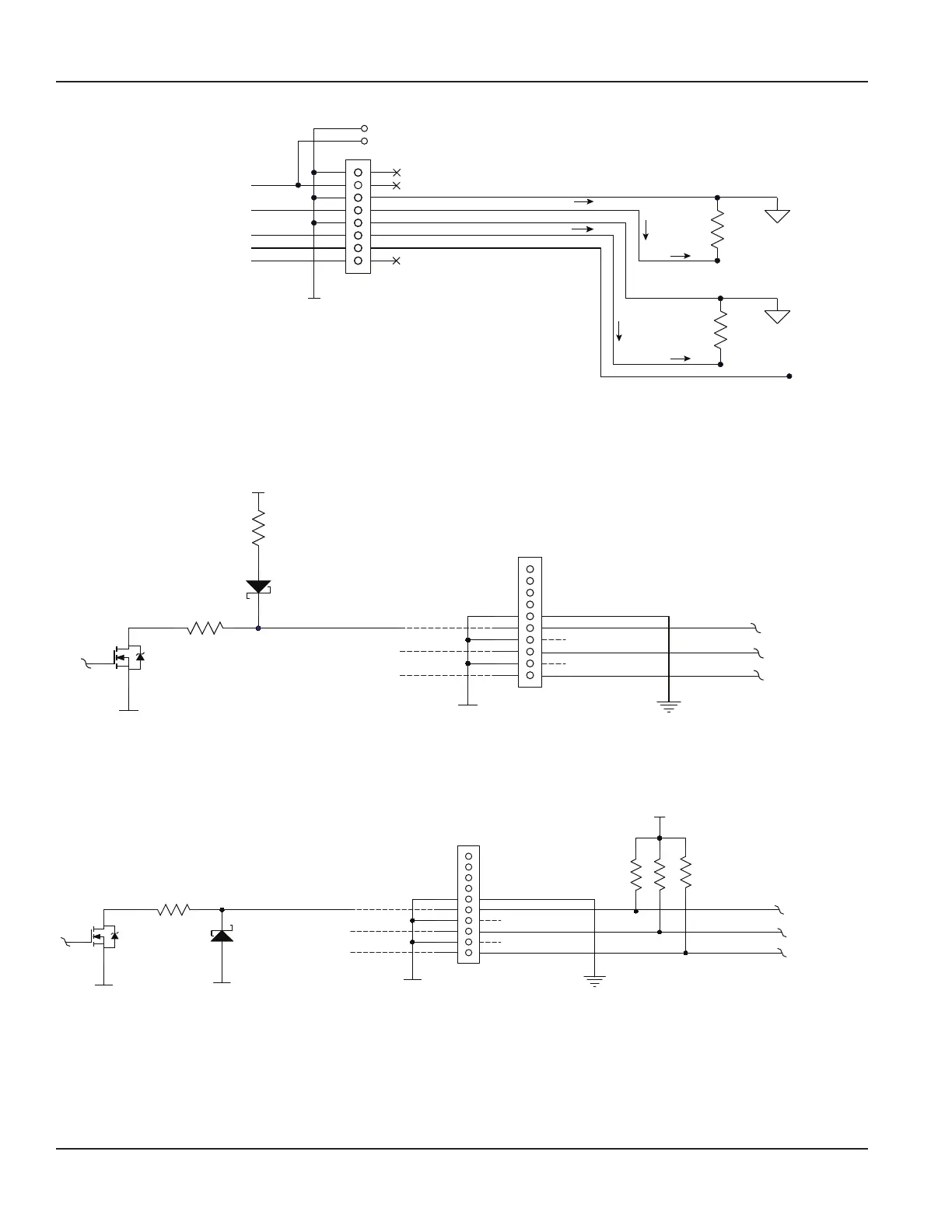
Figure 29: Typical 4 . . . 20 mA interface using external isolated 24V DC source
Digital Outputs Wiring
ISO 24V
10k
R12
10 Ohms
ISO_GND
ISO_GND
Control Output #1
Control Output #2
Control Output #3
TB700
External Equipment
Control Output #1
Control Output #2
Control Output #3
IF REQUIRED
IF REQUIRED
5
6
7
8
9
10
NOTE: Control Output 3
available with Energy
model only.
(Acceptable wire sizes: 28…12 AWG)
Figure 30: Typical control out 1, 2 and 3 interface with internal pullups active
R12
10 Ohms
ISO_GND
ISO_GND
Control Output #1
Control Output #2
Control Output #3
TB700
External Equipment
Control Output #1
Control Output #2
Control Output #3
IF REQUIRED
IF REQUIRED
5
6
7
8
9
10
50 mA max. Sink
ISO_GND
V DC (5 . . . 30V DC)
R-Pullup
R-Pullup
R-Pullup
NOTE: Control Output 3
available with Energy
model only.
(Acceptable wire sizes: 28…12 AWG)
Figure 31: Typical control out 1, 2 and 3 interface with external pullups passive
Wiring the Transmitter
Page 18 October 2019TTM-UM-02222-EN-04
 Loading...