TROUBLESHOOTING
Warning and alarm messages are classified according to NAMUR 107 standards.
Out of Specication Messages
Warning and alarm messages occur when the flow meter is operational, but the readings might be out of specification or an
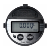
operator might need to take action. If a warning or alarm condition occurs, a warning/alarm icon with code will appear in the
at the bottom of the Home Screen. The flow rate and flow total will continue to be displayed.
Error Messages
An error condition occurs when the flow rate cannot be determined, such as when the signal strength is too low. If an error
condition occurs, the flow rate will be replaced with the "failed" icon, code and description.
If conditions cause multiple messages to occur, all messages will be saved to the history, but some messages may not be
displayed. If an error condition occurs, warning and alarm messages will not be displayed. If multiple errors occur, each error
message will cycle through and be viewable for 5 seconds. Similarly, if multiple warning or alarm conditions occur (but no
error conditions), each message will cycle through and be viewable for 5 seconds.
Warning, Alarm and Error Messages automatically clear when the issue clears.
Check Function Codes
When the meter or outputs are in a test mode, a check function message appears at the bottom of the Home Screen.
View Alarm and Message Buer
Up to 30 alarm or warning message codes are buffered on a first-in-first-out basis. To view the buffer, go to
DIAGNOSTICS > HISTORY.
Warning and Alarm Message Codes
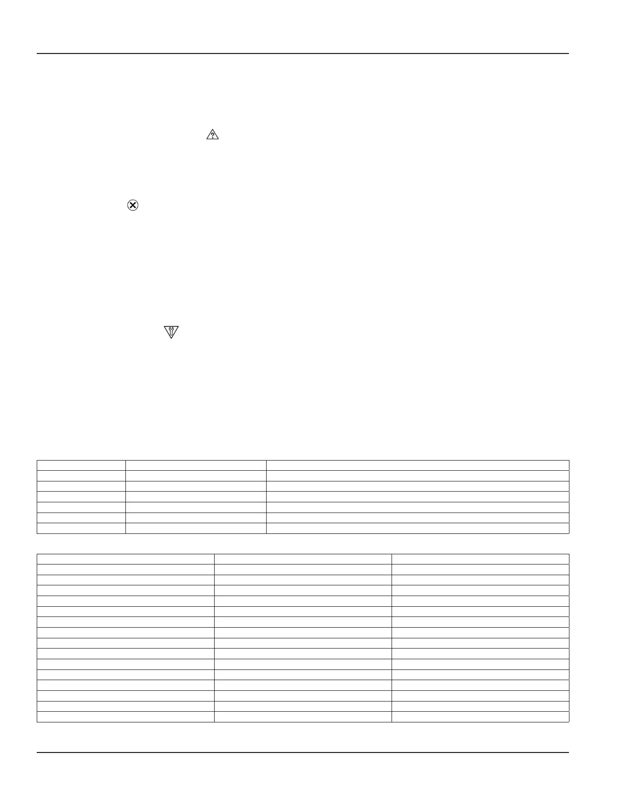
Failure Codes
Code Description Correction
F02 ELECTRONIC ERROR Multiple watchdog timeouts occurred. Contact factory
F03 ELECTRONIC ERROR Voltage levels are out of specification. Reboot transmitter; If error repeats, repair or replace transmitter.
F10 LOW SIGNAL Signal strength is below cutoff. Check for empty pipe, transducer spacing and parameter settings.
F11 HIGH SIGNAL Signal strength is oversaturated. Change transducer mounting for more paths or enable shunt resistor.
F20 RTD #1 ERROR Unable to detect RTD #1. Check wiring to RTD #1 connector.
F21 RTD #2 ERROR Unable to detect RTD #2. Check wiring to RTD #2 connector.
Check Function Codes
Code Description Correction
C01 CURRENT TEST Current output is in test mode. Change Current Output from Test Mode.
C10 OUTPUT #1 FREQUENCY TEST Output #1 is in frequency test mode. Change Output #1 from Test Mode.
C11 OUTPUT #1 PULSE TEST Output #1 is in pulse test mode. Change Output #1 from Test Mode.
C12 OUTPUT #1 SWITCH TEST Output #1 is forced on or off. Change Output #1 from Test Mode.
C20 OUTPUT #2 FREQUENCY TEST Output #2 is in frequency test mode. Change Output #2 from Test Mode.
C21 OUTPUT #2 PULSE TEST Output #2 is in pulse test mode. Change Output #2 from Test Mode.
C22 OUTPUT #2 SWITCH TEST Output #2 is forced on or off. Change Output #2 from Test Mode.
C30 OUTPUT #3 FREQUENCY TEST Output #3 is in frequency test mode. Change Output #3 from Test Mode.
C31 OUTPUT #3 PULSE TEST Output #3 is in pulse test mode. Change Output #3 from Test Mode.
C32 OUTPUT #3 SWITCH TEST Output #3 is forced on or off. Change Output #3 from Test Mode.
C41 AUX #1 PULSE TEST Aux Output #1 is in pulse test mode. Change Aux Output #1 from Test Mode.
C42 AUX #1 SWITCH TEST Aux Output #1 is forced on or off. Change Aux Output #1 from Test Mode.
C51 AUX #2 PULSE TEST Aux Output #2 is in pulse test mode. Change Aux Output #2 from Test Mode.
C52 AUX #2 SWITCH TEST Aux Output #2 is forced on or off. Change Aux Output #2 from Test Mode.
C60 SIMULATION MODE Meter is running flow simulation. Deactivate Simulation Mode.
Troubleshooting
Page 44 October 2019TTM-UM-02222-EN-04

 Loading...