WIRING THE TRANSMITTER
IMPORTANT: Select field wiring means rated for 5° C above the maximum area temperature when it is possible that the
temperature will exceed 55° C.
To access terminal strips for wiring, loosen the 4 enclosure captive screws. Grasp and lift the cover and open it to the left. The
cover remains attached and the left screws act as a hinge.
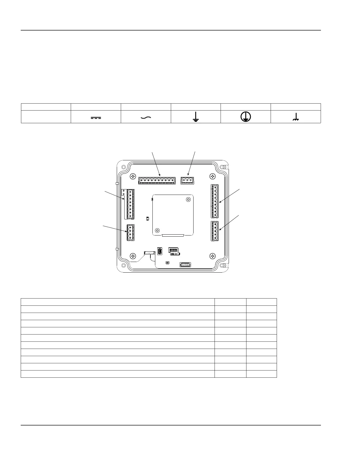
Electrical Symbols
Function Direct Current Alternating Current Earth (Ground) Protective Ground Chassis Ground
Symbol
Figure 22: Electrical symbols
Power
Connector
TB700
Digital I/O
Connector
TB600
Analog
Output
Connector
TB900
RTD
Connector
TB500
BEACON/
AquaCUE
Endpoint
Accessory
Card
TB300
Transducer
CPU
LEDs
MicroSD
Card Holder
USB Mini B
Connector
Figure 23: Wiring connectors
Connection Data
Description Minimum Maximum
Conductor cross section solid 0.2 mm² 2.5 mm²
Conductor cross section flexible 0.2 mm² 2.5 mm²
Conductor cross section flexible, with ferrule without plastic sleeve 0.25 mm² 2.5 mm²
Conductor cross section flexible, with ferrule with plastic sleeve 0.25 mm² 2.5 mm²
Conductor cross section AWG 24 12
2 conductors with same cross section, solid 0.2 mm² 1 mm²
2 conductors with same cross section, stranded 0.2 mm² 1.5 mm²
2 conductors with same cross section, stranded, ferrules without plastic sleeve 0.25 mm² 1 mm²
2 conductors with same cross section, stranded, TWIN ferrules with plastic sleeve 0.5 mm² 1.5 mm²
AWG according to UL/CUL 30 12
Wiring the Transmitter
Page 14 October 2019TTM-UM-02222-EN-04

 Loading...