OTE:N Use suitably certied fittings/plugs to maintain the watertight integrity of the enclosure. Generally, the right conduit
hole (viewed from front) is used for power, the left conduit hole for transducer connections, and the center holes are
used for I/O wiring.
8. Install the wires through the gland nuts and connect the wires to the removable terminal blocks. See “Wiring the
Transmitter” on page14.
9. Wire the transducers to the transmitter.
10. Plug the wired terminal blocks into the main board.
11. Reassemble the cover. Torque the cover screws to 45 in-lb.
12. Set up the meter. See “Initial Meter Setup” on page21 for instructions.
Installing a Meter with a Remote Transmitter and Adjustable Transducers
• Locate the transmitter within the length of the transducer cables supplied or exchange the cable for one of proper length.
• Install the transducers after entering the pipe settings into the transmitter and determining the spacing and
mounting method.
• See Figure 2 on page 6 for enclosure and mounting dimension details. Allow enough room for door swing, maintenance
and conduit entrances.
MPORTANTI
When routing wires to the transmitter, make sure the cables are not twisted, pinched or hanging loosely.
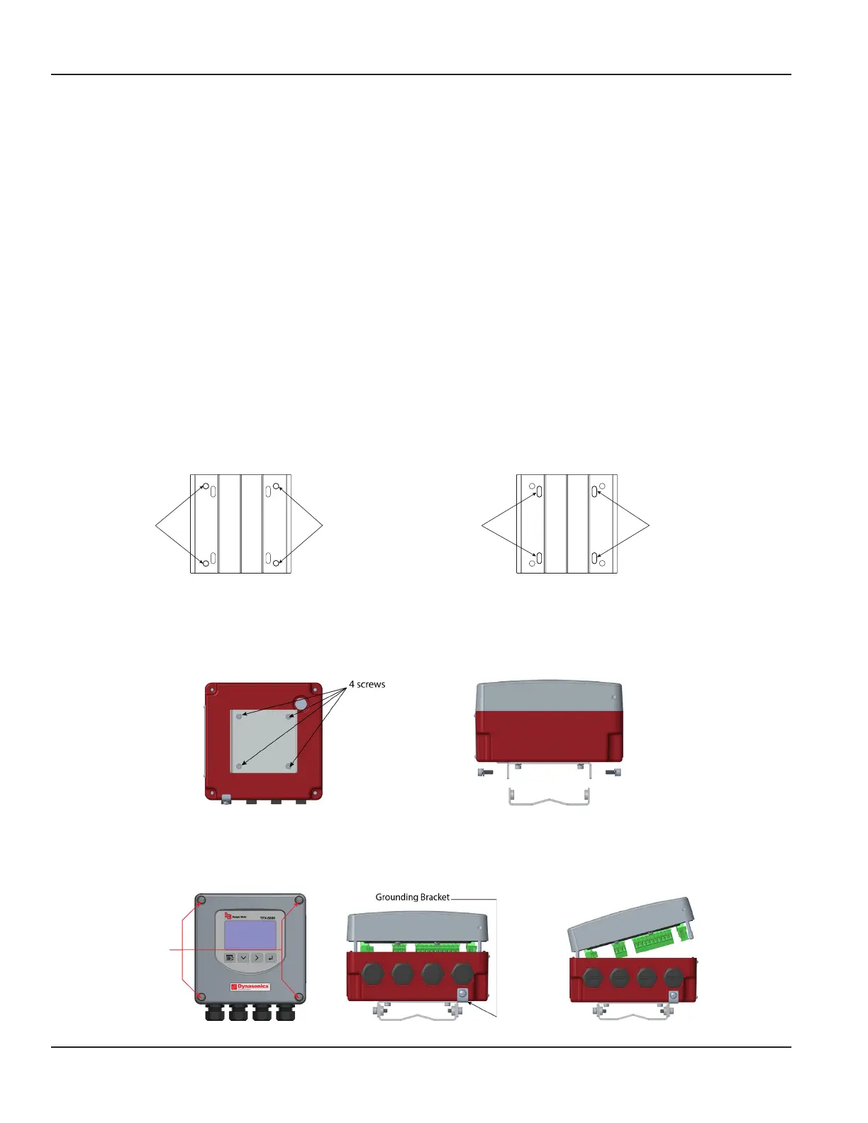
1. Attach the mounting bracket to a wall (with 4 customer-supplied #8 or M4 screws, see “Wall Mount Bracket” on page7
for dimensions) or to a pipe (with mounting straps).
Holes for
Screws for
Holes for
Screws for
Slots for
Straps for
Pipe Mounting
Slots for
Straps for
Pipe Mounting
Figure 13: Wall mount Figure 14: Pipe Mount
2. Align the transmitter's bracket with the mounted bracket. Use a 4 mm hex tool to secure the 4 provided screws from the
sides through the mating holes. See Figure 16.
3. If necessary, you can rotate the mounting bracket in 90° increments to accommodate the nal orientation of the
transmitter. From inside the enclosure, remove the 4 screws holding the bracket. Rotate the bracket and replace the
screws. See Figure 15.
Figure 15: Rotatable adapter plate Figure 16: Secure the bracket
4. Insert a wire for earth ground under the grounding bracket (see Figure 18) and screw it down tight.
5. Partially loosen the 2 enclosure captive screws on the left side of the transmitter cover. Completely loosen the 2 screws on
the right side. Grasp and lift the cover and open it to the left. The cover remains attached and the left screws act as a hinge.
Unscrew
Captive Screws
Figure 17: Captive cover screws Figure 18: Lift cover from base Figure 19: Open cover to the left
Installation
Page 12 October 2019TTM-UM-02222-EN-04

 Loading...