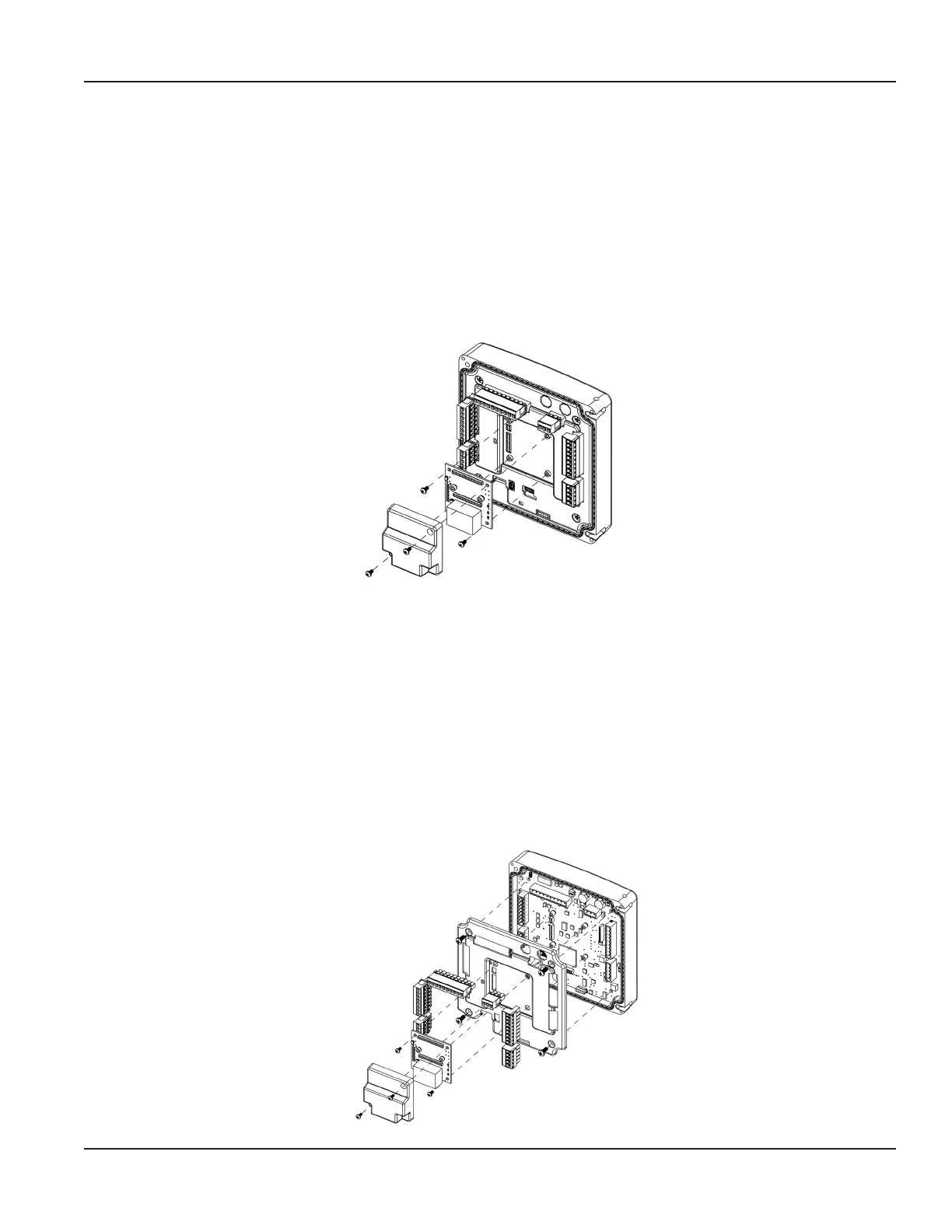
Replacing the Communication or Dry Contact Board
1. Turn o the power.
2. Open the enclosure.
3. Disconnect the wires from the communication board.
4. Remove (2) M3 pan head phillips screws that secure the cover over the communication board.
5. Remove the cover.
6. Remove the remaining (2) M3 pan head phillips screws that secure the communications board.
7. Lift the communications board straight out to unplug from the main board.
Installation is in reverse order, noting the following. To install a new communications board, align the pins with the header on
the main board and gently press straight down. Be careful not to misalign the pins. Do not use excessive force.
Figure 42: Replacing the Communication or Dry Contact Board
Replacing the Main Board
1. Turn o the power.
2. Open the enclosure.
3. Remove the terminal blocks from the header on the main board.
4. If a communications board is present, remove it.
5. Remove the (4) M4 pan head phillips screws that secure the main board and shield.
6. Lift the shield o the main board.
7. Gently pull the main board straight out to disengage it from the display header and remove it from the enclosure lid.
Installation is in reverse order, noting the following. To install a new main board, align the pins on the display header with the
socket on the main board and gently press straight down. Be careful not to misalign the pins. Do not use excessive force.
Figure 43: Replacing the Communication or Dry Contact Board
Replacement Procedures
Page 49 October 2019 TTM-UM-02222-EN-04

 Loading...