AW00123409000 Image Acquisition Control
Basler ace USB 3.0 133
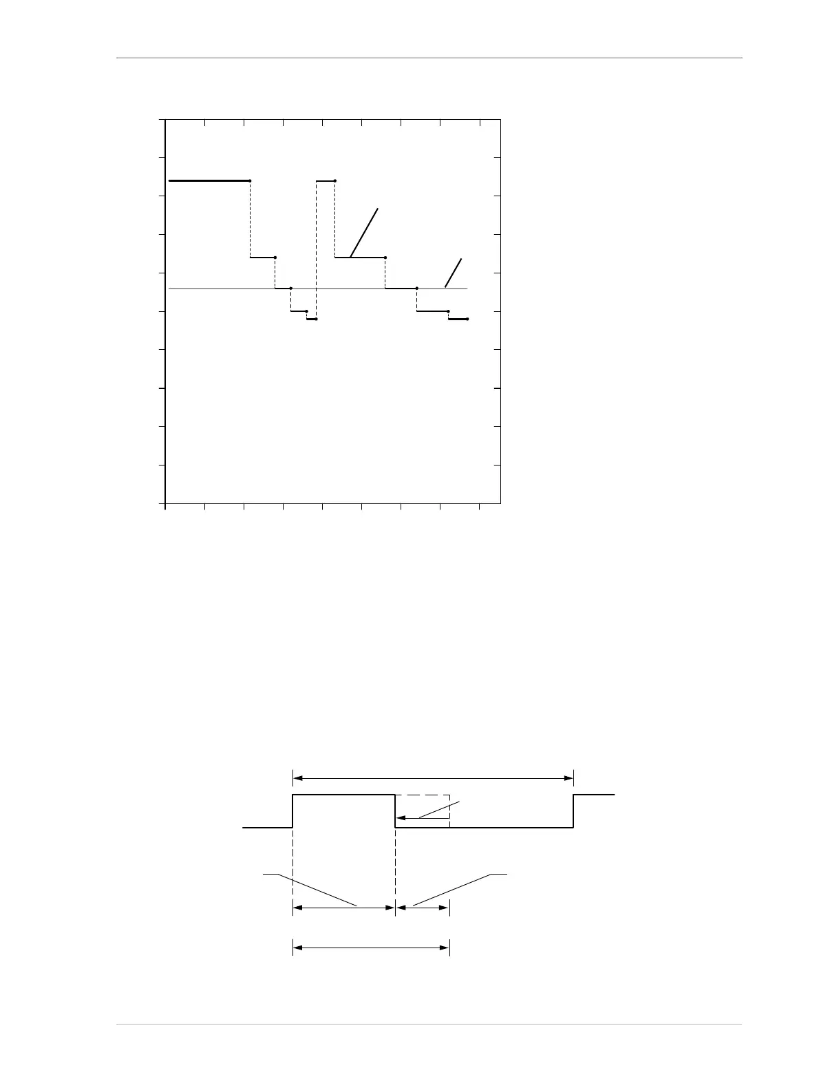
Fig. 59: Exposure Time Offsets Depending on Device Link Throughput (acA200-165u and acA2040-90u Cameras
Only; All 8 bit- and 12 bit-Pixel Formats)
To obtain the wanted exposure time with trigger width exposure mode:
1. Subtract the value for C
4
(see Table 32 and Figure 59) that applies to your camera model, from
the wanted exposure time.
2. Use the resulting time as the signal high time for the ExFSTrig signal if the signal is not
inverted or as the low time if the signal is inverted.
Fig. 60: Trigger Width Exposure with Adjusted Rising Edge Triggering; (Exposure Start Delay Is Omitted)
50
45
40
35
30
25
20
15
10
5
0
1000 200 300 400
Device Link Throughput [MByte/s]
Exposure Time Offset, C
4
[µs]
acA2000-165 and
acA2040-90; 8 bit
acA1920-155;
8 bit, 12 bit
acA2000-165 and
acA2040-90; 12 bit
ExFSTrig Signal Period
Offset-adjusted
ExFSTrig Signal
Exposure (Total; Wanted)
Exposure, Controlled
by Timing-adjusted
ExFSTrig Signal
Exposure, controlled by
Exposure Time Offset; C
4
Offset Adjustment