A
B
C
D
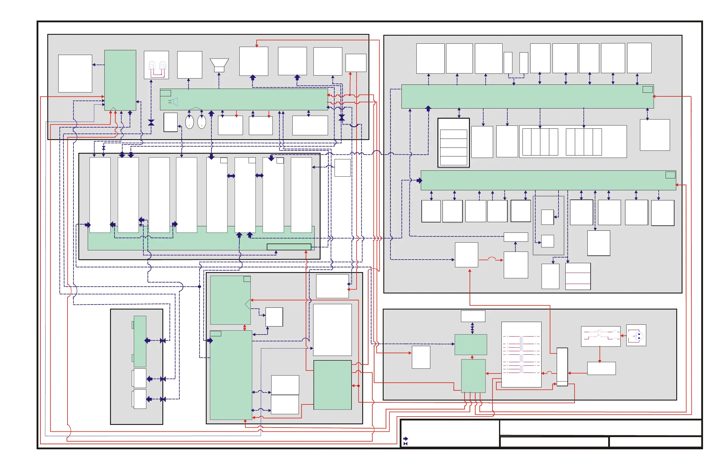
Arena Interconnect Diagram
157-1278-586
Rev A 11-03-03
Input/Output Hydraulics Power Board
Hour
Meter
Blood Leak
Detector
OLHDF
Purge
Valve #1
(Optional)
Powder Air
Trap Level
Sensor
(optional)
Powder
Cartridge
Holder Reed
Switch
(optional)
Dialysate
Flow
Sensor
(Optional)
Concentrate
Interlock
Main Level
Sensor
Rinse
Block
Interlock
Solid
State
Relay
Safety
Thermostat
Recirculation
Valve
Bypass Valve
Flow Control
Valve
Primary
Conductivity
Probe
PH33
PH35
PG10
J1
PG16
PG18
PG23
PG24
PG25
PG03
PG04
PG02
PG05
PG06
PG07
PG08
PG69
PG70
PG09
PG11
PG12
PH37
PH37
PH34
PI45
PH34
PH34
P2
DB9
CN13
PH36 PH38 PH40 PH40 PH42
PH02
PH39PH36 PH36
Dialysate
Pressure
Transducer
2
1
Valve 1
Valve 4
Valve 2
Valve 3
Valve 5
Valve 8
Valve 4
UF Removal
Meter
Valve 3
Valve 2
Valve 1
Valve 6
Valve 7
Flow
Equalizer
Assembly
C
Cond.
Probe
(Not Used)
UF/ Proportioning Power Board
Dialysate
Pressure
Relief
Valve
EOS
Sensors
Dialysate
Pump
Deair.
Pump
B Conc.
Pump
A Conc.
Pump
B
Cond.
Probe
A
Cond.
Probe
Supply
Pump
Hydraulics Module
PH
PG
PG01
OLHDF
Purge
Valve #2
(Optional)
Citric
Acid Valve
(Optional)
Red Solid Line- Power
Blue Dotted Line-Communication
Ribbon Cable
Connector
Green blocks- Printed Circuit Boards
Powder
Air Trap
Valve
Powder
Prime
Valves
Heater
Thermistor
PM02
PM66
P1 & P2
CB2
P3
P4
F1
JM19
HDF Power
Supply Board
(optional)
HDF Scale
(optional)
Unregulated
Power
Supply
CB120 A or 10 A
Isolation
Transformer
Terminal
Block
Mains Circuit
Breaker
Power Cord
RFI Filter
Base
Fan
PI45
PI43
PK51
PK49
PI49
PI63
PI44
PI02
PI50
TB2
TB1
+5 VDC Alarm Lamp Power
Blood
Pressure
Monitor
(optional)
Switching
Power
Supply
Blood/
Saline
Detector
Air
Detector
Venous
Line Clamp
Driver Board
Input/Output
Electronics
Power Board
Venous
Line
Clamp
Lower Chassis
PI
Sonalert
Alarm Lamp
Arterial
Rotary
Line
Clamp
(optional)
Blood Pump
Controller Bd.
UF-Proportioning
Controller Bd.
Input/Output
Controller Bd.
Memory Bd.
Non-volatile SRAM, DIP Switch
SDRAM
Flash Compact Memory
Card Cage
Hemavision Bd. (optional)
4-Comm (Touch-Screen) Bd.
Slot #1
+5,+12, & -12 VDC LED Indicators
Slot #5 Slot #7
PD43
PB25
PB52
PD52
PD52
PC52
P2
P2
P1
CN5
CN5
JP3
J9
J2
CN1
CN13
PC01
Slot #6
PD35
J1
Filter
PW1
Speaker
k
r
Sp
ea e
Slot #8Slot #4
Single Board Computer
Slot #2
Slot #3
Empty
PB
PK
PD
PC
Passive Backplane
J3
J5
J9
J6
J7
J1
J8
J2
Membrane
Panel
Switches
PF24
PF27
PF02
PF23
P3
P2
P2
P3
PF31
PF20
PF32
PF21
NA
PF22
PF50
PF25
PF26
Touch
Screen
Optional
Regulator
+20 VDC
15-Inch Color
LCD display
Alarm
Lamp
Venous
Arterial
Secondary
Blood Pump
(Optional)
Hema
Clip
Blood Pump Power Bd.
ART Transducer JF28
VEN Transducer JF29
SND Transducer JF30
Cabinet Temp. Sensor
Primary
Blood
Pump
Heparin Pump
Speaker
Level
Adjust
Motor And
Valves
Patient
Data
Card
Reader
Peripheral
Interface
Board
Upper Chassis
PF
Sonalert
Service
Reed
Switch
+12 VDC
Cabinet
Temperature
Sensor
RJ45
Sodium
Button
(Optional)
Passive
Rear
Panel
Int.
Bd.
3-Light
Status
Lamp
Serial
Comm.
Ethernet
RS
232
Peripheral Devices
Rear Connection Panel