5. Electronics
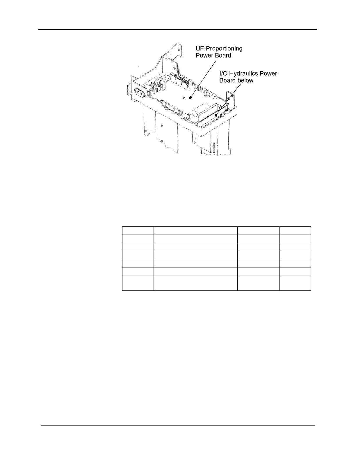
Figure 5-18. UF-Proportioning and I/O Hydraulic Power Board Locations
5.6.1 Fuses
This board incorporates 17 fuses as shown in Table 5-5. Fuses
may be removed by grasping them in the center with small pliers.
Table 5-5. UF-Proportioning Power Board Fuses
FUSE FUSE CIRCUIT PART NO. RATING
F1 +24 VDC 6001276132 10 A
F2 +12 VDC 6001276129 0.25 A
F3 +5 VDC 6001276130 0.50 A
F4 -12 VDC 6001276129 0.25 A
F5 - F16 Concentrate pump windings 6001276129 0.25 A
F17 +35 VDC step-up regulator
for both concentrate pumps
6001276131 2.0 A
Caution
Do not remove fuse from or insert fuses into the UF-
Proportioning Power board while power is applied to the
board.
Figure 5-19 shows Fuse F2 removed from the board, while Fuses
F3 and F4 are installed. A typical fuse is also shown. Fuses may
be continuity tested out of circuit with an ohm meter. Spare fuses
may be packaged in a special holder for added protection. Fuses
must be removed from that holder before use. See Figure 5-20 for
fuses, shown in green.
157-1278-912 Rev A 5-31
November 2003