Arena Service Manual
10.4 ROTOR ASSEMBLY
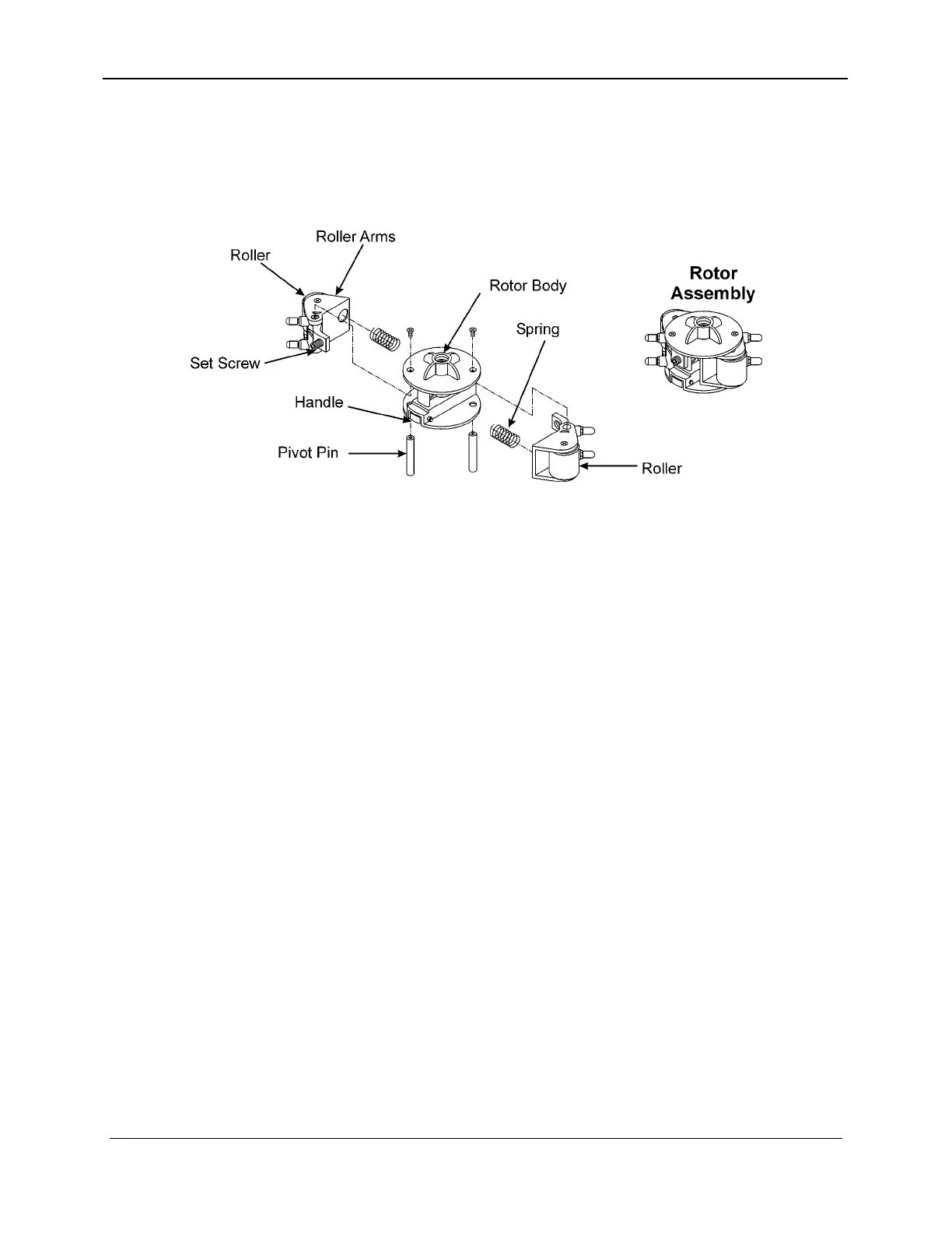
There are seven major parts within the blood pump rotor assembly:
handle, rotor body, rollers, roller arms, pivot pins, set screws and
springs. (See Figure 10-5).
Figure 10-5. Rotor Assembly Exploded View
The handle is mounted on the front of the assembly and can be
used for manual pumping.
The rollers are mounted on the roller arm, which connects to the
rotor body via a pivot pin. The springs are placed between the
roller arms and the rotor.
The springs apply pressure on the roller arm pushing the rollers out
from the rotor.
The setscrews are mounted on the roller arm. Adjusting the
setscrews limits the outward roller arm travel. When the setscrew
is turned clockwise the roller is moved toward the rotor causing
less pressure on the tubing segment. When the set screw is turned
counter-clockwise the roller is moved outward from the rotor
causing more pressure on the tubing segment.
When the roller assembly is adjusted properly the correct pressure
will be applied to the blood pump tubing segment.
For more information regarding blood pump adjustment go to
Blood Pump Rotor Occlusion, Section 18.6.1.
10-8 157-1278-917 Rev A
April 2004