Arena Service Manual
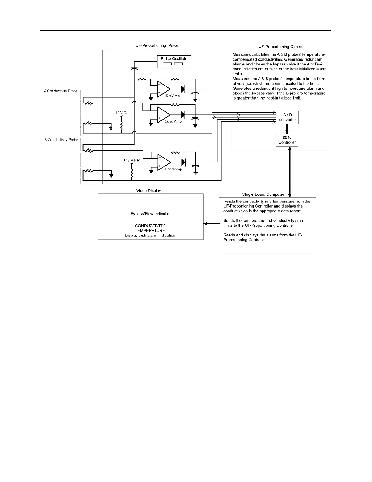
Figure 7-8. UF-Proportioning Temperature / Conductivity Block Diagram
7.6.3 Conductivity Calibration
Refer to Section 18, Calibration/Adjustments, for the actual
calibration procedure.
The conductivity probes are calibrated in the Calibration Mode.
The resistance of each probe is measured at a known conductivity
and temperature (by the use of an external reference meter) for the
scaling of the probe's base resistance in the outlet relationship.
During the calibration, when the primary conductivity is stable, the
three conductivities are set equal to an independent conductivity
reference meter through the use of the three programmable gain
constants contained within the two controllers.
The conductivity is measured by the controllers using circuitry
which measures an AC resistance between each pair of the
conductivity probe's electrodes. One electrode of each
conductivity probe is stimulated with a 1 kHz AC voltage while
the other is held at virtual ground (current sense electrode). Two
DC voltages are produced by the circuit, one of which is
7-16 157-1278-914 Rev A
January 2004