DESCRIPTIONDESCRIPTIONREVREV DATEDATEECO #ECO # APPROVEDAPPROVED
DWG No.DWG No.
11
AA
223344
BB
CC
DDDD
CC
BB
AA
44 33 11
BB
SHEETSHEET OFOF
SCALESCALE
REVREVDWG No.DWG No.
DATEDATEDRAFTERDRAFTER
DO NOT SCALE DRAWINGDO NOT SCALE DRAWING
BREAK ALL SHARP CORNERSBREAK ALL SHARP CORNERS
.005/.010 CHAMFER/RADIUS.005/.010 CHAMFER/RADIUS
CONFIDENTIALCONFIDENTIAL
INFORMATIONINFORMATION
SURFACE FINISH:SURFACE FINISH:
UNLESS OTHERWISE SPECIFIEDUNLESS OTHERWISE SPECIFIED
DIMENSIONS ARE IN INCHES.DIMENSIONS ARE IN INCHES.
TOLERANCES ARE:TOLERANCES ARE:
ANGLESANGLESDECIMALSDECIMALS
6363
DESCRIPTIONDESCRIPTION
MATERIAL / FINISH / SPECIFICATIONSMATERIAL / FINISH / SPECIFICATIONS
CorelDRAW FILECorelDRAW FILE
± .5^
.XX ± .01
.XXX ± .005
AAMI Standard
Water
Water
Pressure
Regulator
Variable Positive PSI
Not Adjustable
Variable Positive PSI
Not Adjustable
Dialysate
Pressure
Starts Here
Dialysate
Pressure
Starts Here
Heater
Drain Line
Drain
Air Gap
Water Temp Control
Thermistor
500 mL/min500 mL/min
Speed Varies
with Flow
74m
Filter
74m
Filter
“A”
Concentrate
Pump
“A”
Concentrate
Regulator
(Optional)
“B”
Concentrate
Regulator
(Optional)
Air Gap
Chamber
Mixer
“A” Conductivity
Thermistor/Probe Set
Air
Removal
Pump
Hall-effect
Level
Sensor
(open/close
the water valve)
Air
Trap
Drain
Vent
to
Atmosphere
“B” Conductivity
Probe/Thermistor Set
Dialysate Conductivity
Probe/Thermistor Set
Flow Sensor
Water
On /Off
Valve
Heat
Exchanger
Heat
Clean
Recirculation
Valve
“B” Mix
Chamber
Rinse Ports
With
Proximity
Sensors
Disinfect
Loop
Supply
Pump
(lower
middle)
150m
Particle
Filter
Flow
Equalizer
Bracket
Blood
Leak
Detector
2
1
End-of-Stroke
Sensors
True
Check Valve
Rinse
Block
Dialysate
Pressure
Pump
(left side)
UF Removal
Regulator
UF Flow
Meter
UF Drain Line
Connector
150m
Particle
Filter
Output
Pressure
Equalizer
Bypass Valve (cycling during disinfection mode)
Dialysate
Pressure
Transducer
Flow
Restriction
Flow
Restriction
Drain
Supply Regulator
X’s flow
Dialysate Monitoring Manifold
(Also called “Final Manifold”,
“Dialysate Manifold” or “Primary
Manifold”)
C1C1
C2C2C3C3
C4C4
5
3
1144
8
2
77
66
33
11
44
22
{
1.5
mL
when
full
1.5
mL
when
full
114
mL
when
full
114
mL
when
full
“B”
Concentrate
Pump
-500
mmHg
-500
mmHg
Supply
Manifold
X
X
X X
500 mL/min500 mL/min
X
500 mL/min500 mL/min
Magnet
711
114
mL
when
full
114
mL
when
full
Input
Pressure
Equalizer
Connector
Safety
Thermistor
Connector
Air Removal
Sprayer
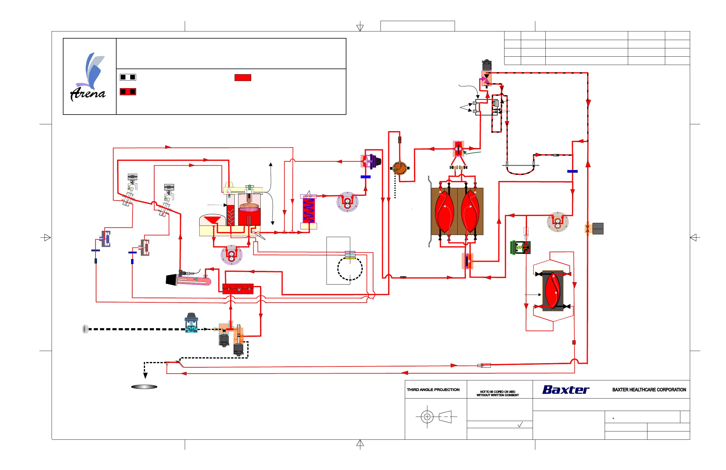
Arena Hydraulics Disinfection Mode Diagram
157-1278-938
A
None
K.Austin
3-02-04
1 2
Recirculation Phase for Heat Clean or Dwell Disinfectants
Red: Heat Clean and
Dwell Disinfectant
Black Dots: No Flow in this Mode
Black Dots and Red: Flow cycles On & Off
Rinse Valve
(Dialysate Pressure Relief
Valve)
Disinfection Mode