Arena Service Manual
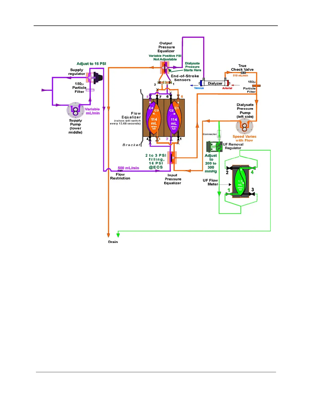
Figure 8-5. Ultrafiltration System Flow Diagram
Note
For clarity purposes, this hydraulic diagram is simplified and does
not show the" B" Mix Chamber in the Supply Pump Recirculation
Loop, the Dialysate Manifold and Bypass Valve between the
Output Pressure Equalizer and the dialyzer, the Blood Leak
Detector after the Output Pressure Equalizer, and the Flow
Equalizer. Please refer to the drawing at the end of Section 4,
Hydraulic Theory, for greater detail.
8.3.1 Supply Pump
The supply pump fills the fresh dialysate side of the flow equalizer
with fluid. The supply pump pumps at a rate slightly higher than
the dialysate flow rate set by the operator. This extra flow ensures
an adequate supply of solution to fill the flow equalizer. The extra
fluid is looped back to the pump inlet via the supply regulator. For
8-8 157-1278-915 Rev A
January 2004