Arena Service Manual
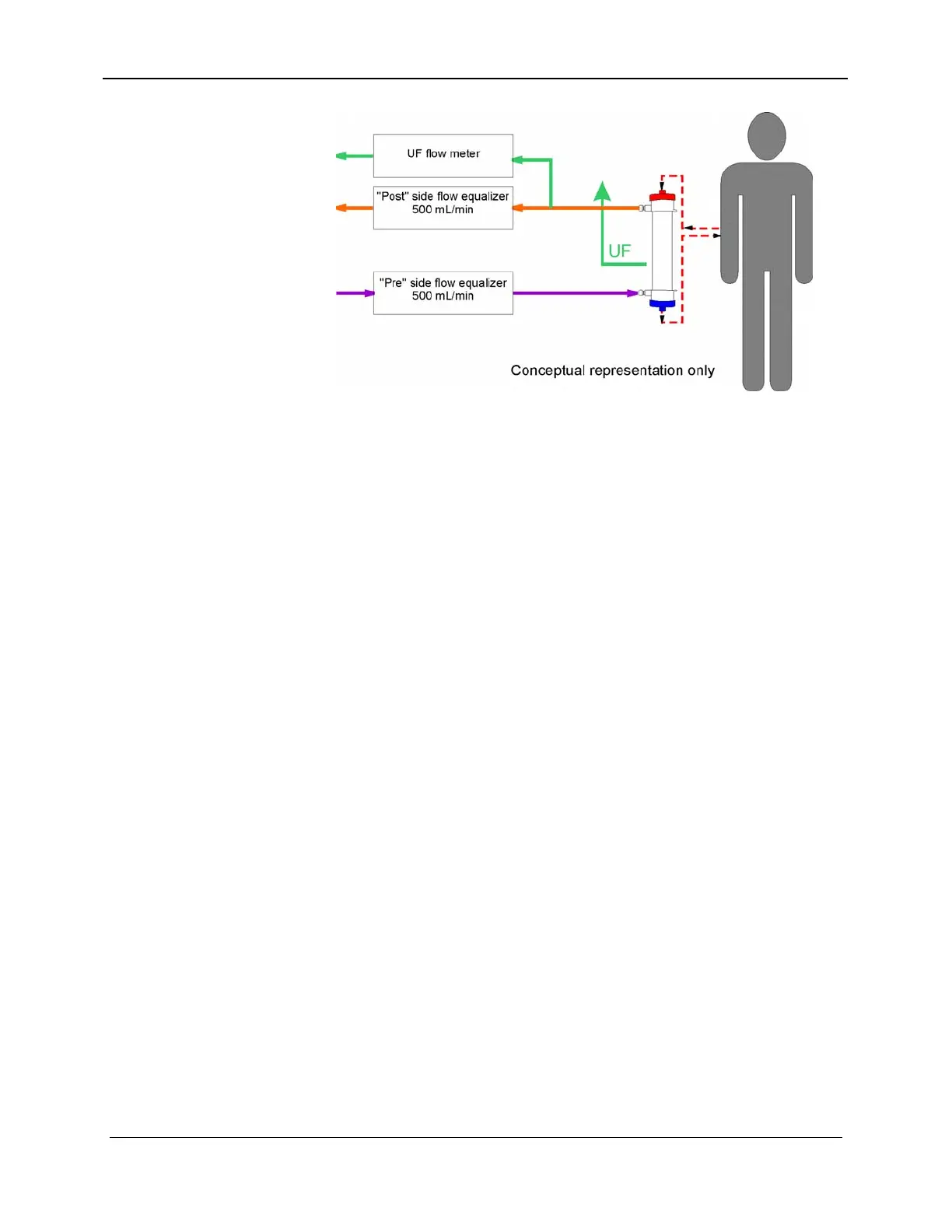
Figure 8-2. UF Flow Meter
The flow through the UF flow meter is displayed in the UF RATE
window. The fluid that passes through the UF flow meter is not
entirely ultrafiltrate. It is volumetrically equivalent to the patient’s
ultrafiltrate. The total volume of fluid removed from the patient is
continuously displayed throughout the treatment in the UF
REMOVED window.
8.2 UF REMOVAL
The UF–Proportioning system controls the UF removal rate by
controlling the time between the switching of the UF removal
metering device valves. The UF-Proportioning system controls the
accumulated UF volume by counting the number of UF removal
meter strokes.
Since the UF removal metering device volume is calibrated in the
Calibration Mode (Section 18, Calibration / Adjustments), the rate
which the host (Pentium microprocessor) passes to the UF–
Proportioning controller (number of seconds between valve
switches) is scaled so that the UF removal rate entered by the user
is achieved.
The UF removal volume entered by the user is scaled by the UF
metering device's stroke volume to a number of UF meter strokes.
The host passes the number of UF meter strokes to the UF-
Proportioning controller. The UF-Proportioning Controller will
then control the UF-Proportioning Power board to switch the UF
removal meter valves and decrement the stroke number, at the
desired rate, as long as the stroke number is greater than zero. The
Host can then calculate the UF removal volume accumulated by
subtracting the number of UF strokes remaining, scaled by the
stroke volume, from the operator entered desired UF removal
volume. The accumulated volume is displayed during the Dialyze
8-4 157-1278-915 Rev A
January 2004