13. Blood/Saline & Air Detectors
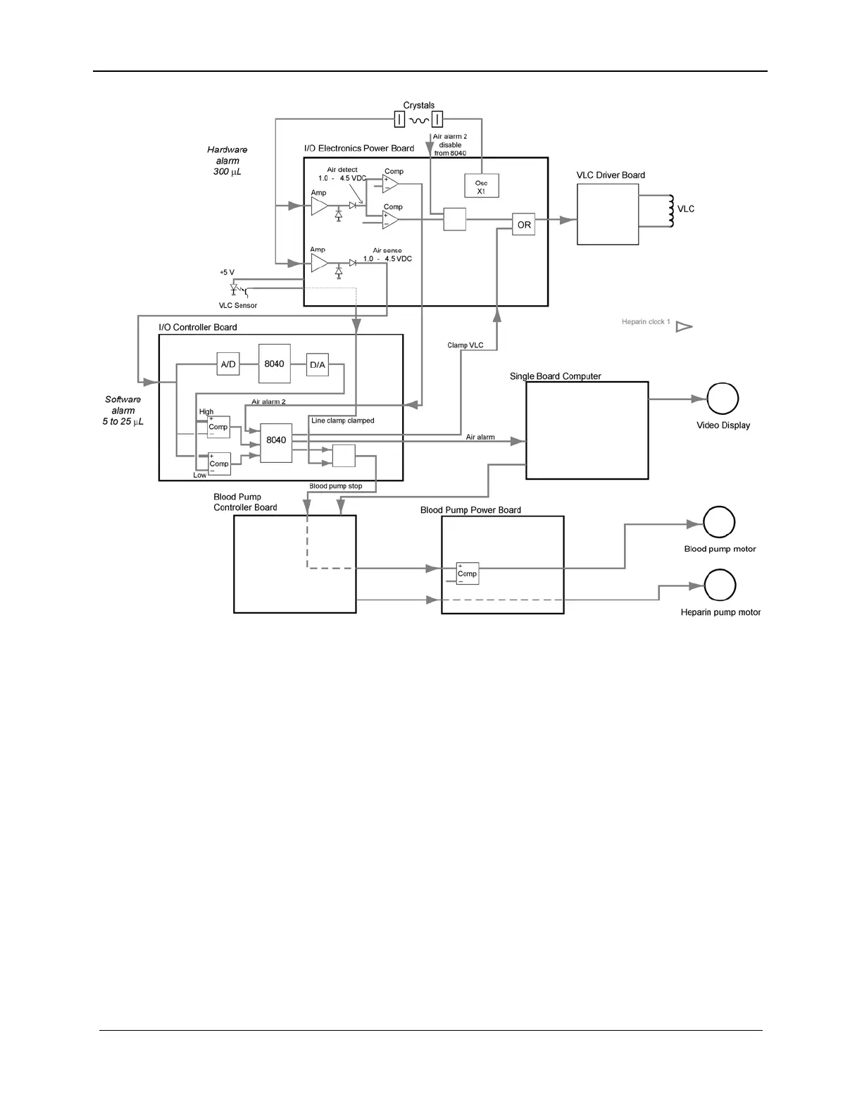
Figure 13-3. Air Detector Block Diagram
The air detector assembly utilizes a set of 2 MHz piezo crystals.
One crystal functions as an ultrasonic transmitter and the second
crystal functions as a receiver. The emitter and receiver are
housed in identical assemblies. The emitter is driven by a 2 MHz
square wave that is derived from a crystal oscillator (X1 and
related circuitry) located on the I/O Electronics Power Board.
When there is fluid in the blood line between the crystal
assemblies, the 2 MHz signal is coupled to the receiver assembly.
The return signal from the receiver assembly is amplified (U9 and
U10) and rectified by two independent circuits also located on the
I/O Electronics Power Board. The resulting signal is a DC signal
of 1.0 to 4.5 VDC. These DC output levels are monitored using
two different methods, software and hardware, each generating a
specific alarm. See Sections 13.2.1.1 and 13.2.1.2.
13.2.1.1 Software Alarm Detection (Primary Alarm)
One output is fed from the I/O Electronics Power Board to an A-
to-D converter and read by the I/O Controller Board. This value is
157-1278-920 Rev A 13-5
April 2004