MX08 Multichannel Weighing System, Technical Manual, Rev. 2.5 Page 15 of 144
3. INSTALLATION
PRECAUTION: Please read this manual carefully before installation of the instrument.
Applying the recommendations in this section will increase your system reliability and long
term performance.
3.1. Recommendations
3.1.1. Control Cabinet Design
Warning: Please care the following warnings for designing the control cabinet which will
increase your system reliability.
The control cabinet should be designed so that MX08 AD Analog Digitizer can operate
safely. The panel should be placed clean area, not getting direct sun light if possible, with
a temperature between -10 ºC and +40 ºC, humidity not exceeding 85% non-condensing.
All external cables should be installed safely to avoid mechanical damages.
MX08 instruments are very low level signal measuring, I/O and gateway units. To avoid
electrical noise, MX08 should be separated from the equipments that produce electrical
noise. Preferable use metal cabinet against radio frequency interference and the cabinet
shall be connected to ground against the electromagnetic disturbances. Load cell cable
trays must be separated from others, if possible. If there are noise-generating equipments
such as heavy load switches, motor control equipments, inductive loads etc., please be
careful against the EMC interference in the cabinet. If possible protect MX08 instruments
with the faraday cage or install them in separate section or install them far a way from this
kind of equipments. Connect parallel reverse diodes to the DC inductive loads like relays,
solenoids etc. to minimize voltage peaks on the DC power lines.
3.1.2. Cabling
All cables coming to the control cabinet shall be shielded. Please use separate cable trays
for these low signal level cables. Distance from load cell cables, interface cables and DC
power supply cables to power line cables shall be minimum 50 cm.
3.2. Mechanical Installation
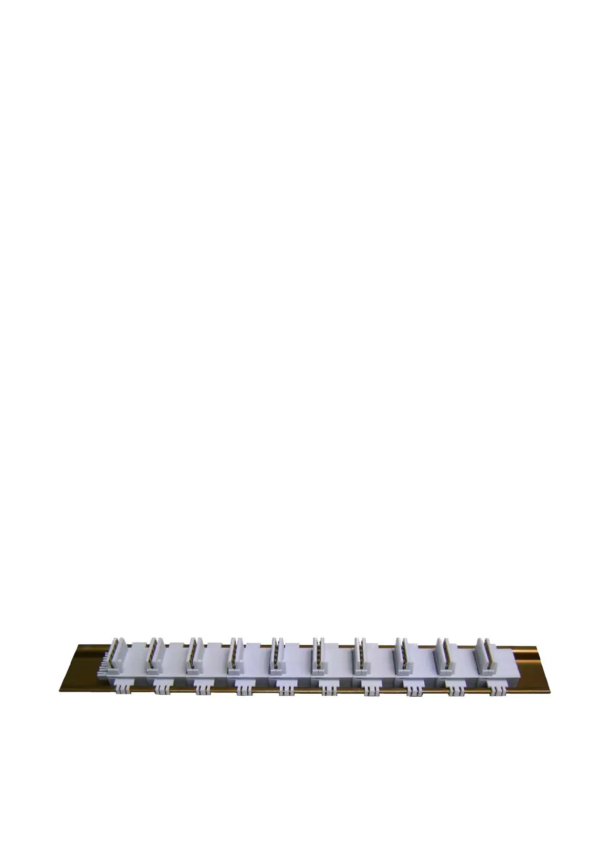
After interior designing the control panel and installing DIN rails according to the
recommendation in Section 2.1, install N-Bus connectors on the DIN rail as seen in the
Figure 2.1.
Figure 2.1 - N-Bus connectors on DIN rail
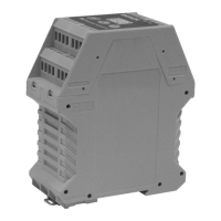
Place the instruments on DIN rail for making N-bus connection between MX08 instruments
as seen Figure 2.2. Be sure that the mechanical installation and N-Bus connection of the
instruments are done properly.