MX08 Multichannel Weighing System, Technical Manual, Rev. 2.5 Page 35 of 144
The meanings of these LEDs in operation are given below.
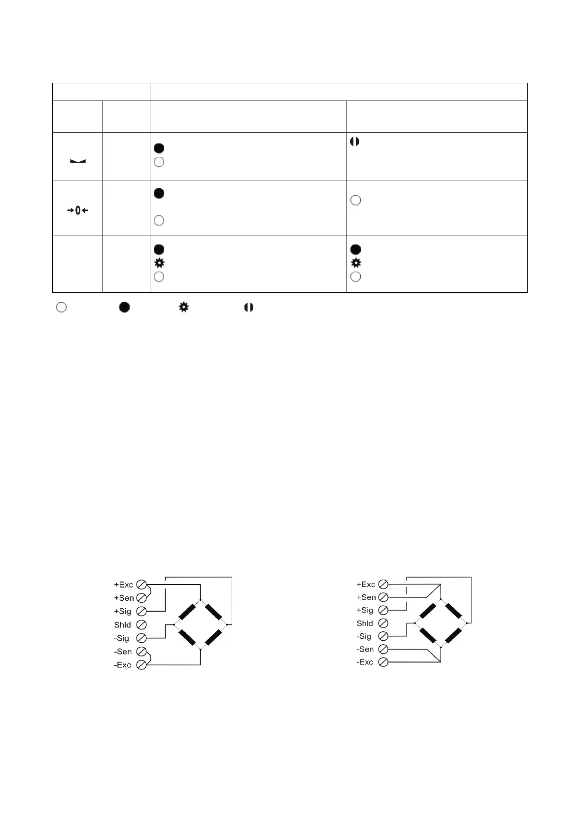
Symbol Name Weight / Force Count
Stable
Stable
Unstable ( Dynamic )
Blanks for 0.3 seconds in 2
seconds period.
( No stable indication )
Centre
of Zero
in the centre of zero range
( -0.25 e < w < 0.25 e )
Out of centre of zero range
Always blank
( No centre of zero indication )
Err
Error
( * )
ADC conversion error
Digital processing error
No error
ADC conversion error
Digital processing error
No error
Blank Light Flash Blank for 0.3 second
( * ) : Refer to the error table in Section 4.5.
Table 4.1 - Annunciater LEDs
5.2. Electrical Connection
Load cell Connection:
To avoid damages, the load cell wiring should be made carefully before energizing the
instrument. The input resistance of the connected load cells should fit the instrument
specification you have. In 4-wire installations the sense and excitation pins with the same
polarity should be short circuited at the connector side. If you have junction box in your
system, use 6 wire cable between MX08 AD and the junction box, and short circuit these
pins at junction box for higher accuracy.
4 wire load cell connection
6 wire load cell connection
Warning: Connect the load cell cable shield to the reference ground or shield pin of the
load cell connector.