1 – Introduction
17
1.5 Conventions
1.5.1 User Interface
Screen buttons are shown in bold (e.g., select Save or select OK).
System prompts and messages are shown in a monospaced typeface (e.g., Report By does not
apply ).
Various displays are named in initial capital letters (e.g., Vial Entry display). Fields are shown as they
appear on the displays (e.g., Accession).
1.5.2 Symbols and Connections Used on the Equipment
The following symbols and connections are used on the BD BACTEC FX instrument:
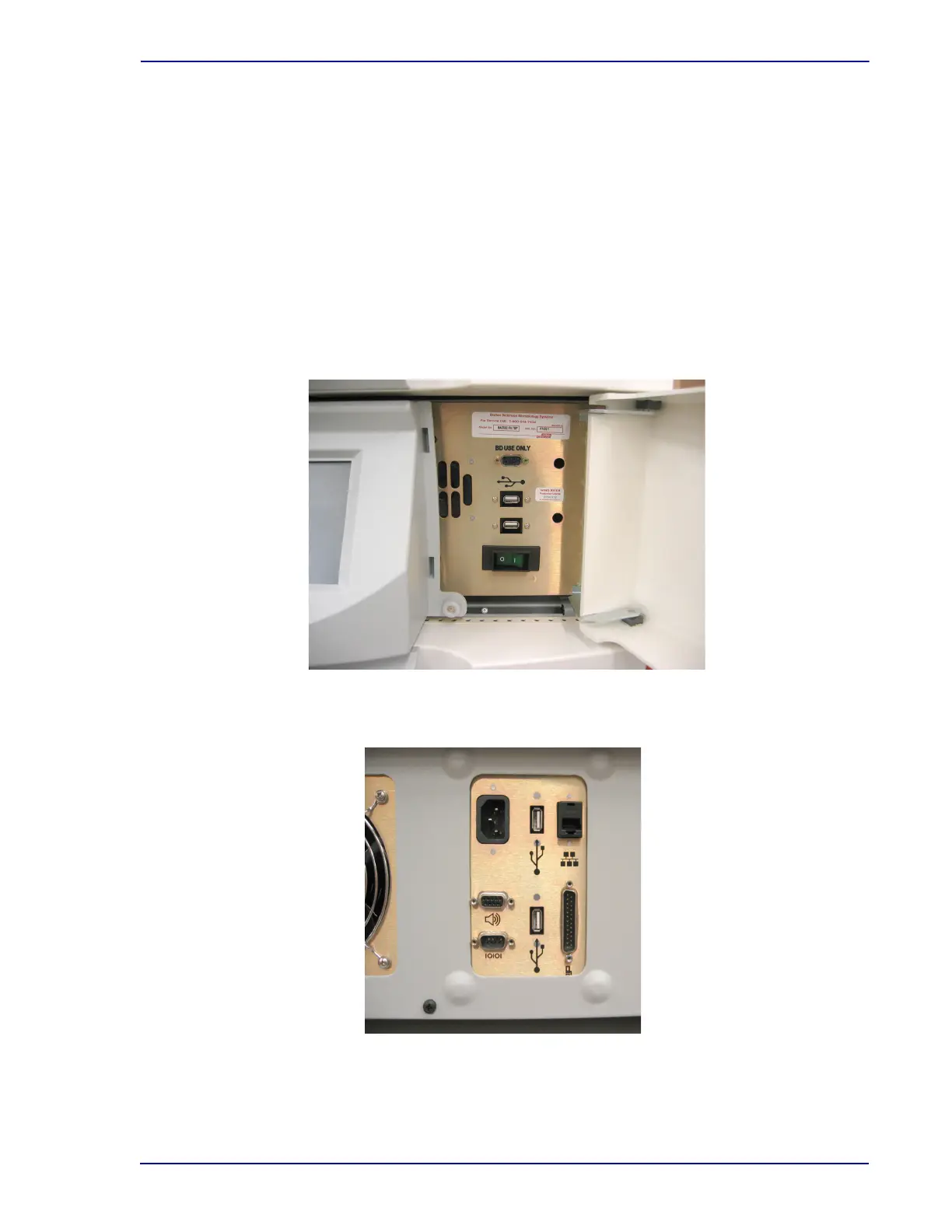
Figure 1-3 – Front Connections
At center of photo, 9-pin serial connector (top); two USB connectors (middle); power switch (bottom).
Figure 1-4 – Top Rear Connections
Clockwise from top left: AC Power connector; USB connector; Network (BD EpiCenter) connector;
Stack connector; USB connector; Serial (LIS) connector; Remote Alarm connector