2-4
TotalAlert Innity™ HTM Medical Gas Notication System
4107 9016 60.01
eld wiring. Alarm panels require 115 to 230VAC
50/60Hz 250mA mains power. Refer to HTM Central,
Area, Combination Wiring Diagrams (Section 3).
For HTM 02-01 compliance, alarm panel must be
connected to the essential power supply of the
electrical system.
1. Remove the four screws from the plastic power
supply shield
2. Remove the plastic shield from the power supply
3. Connect incoming Live and Neutral wires to the
terminal block. Mains Earth wire connects to the
ring terminal provided on the backbox grounding
stud.
4. DO NOT remove or alter the green factory installed
earth wire from the terminal block to the backbox.
5. Reinstall the plastic power supply shield while
making sure all high voltage wires are contained
within the plastic shield.
6. Secure the plastic shield with four screws.
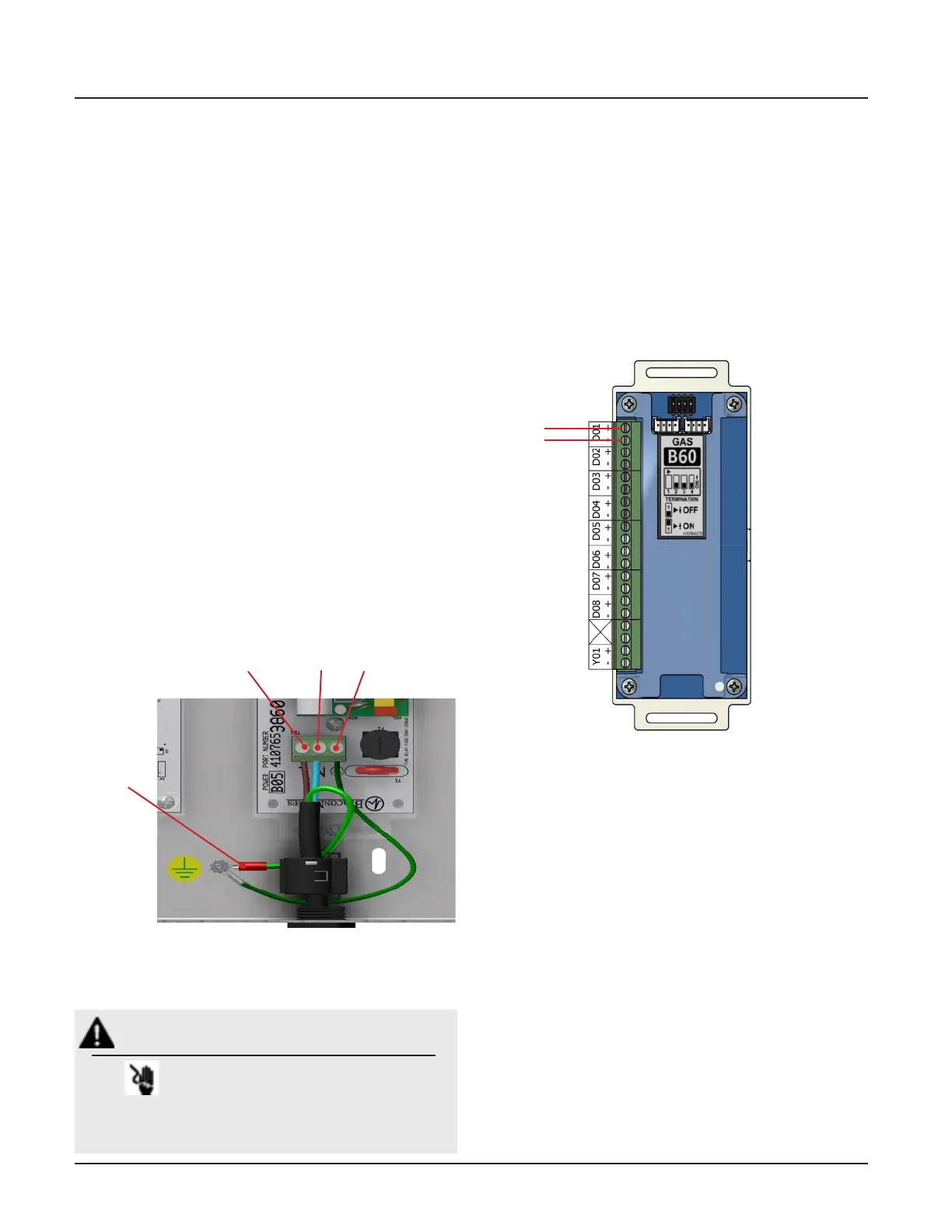
2.3.5 B60 Gas Input Board
An Area alarm has 8 Gas Inputs. Signals are numbered
D01 thru D08. There is a single relay output for general
gas fault notication.
1. Identify each pair of twisted gas sensor wires inside
the alarm backbox (Figure 2.6).
2. Connect each pair of sensor wires to terminal
blocks noting the correct polarity Red(+), Black (-).
HTM Area Wiring Diagram (Section 3.2).
WARNING:
RISK OF ELECTRICK SHOCK
Disconnect power at the circuit breaker before
removing power supply shield.
Figure 2.6: B60 Board Wire Routing
Figure 2.5: Supply Power Wiring
Neutral
Chassis Earth
Live
Mains Earth