4-43
TotalAlert Innity™ HTM Medical Gas Notication System
4107 9016 60.01
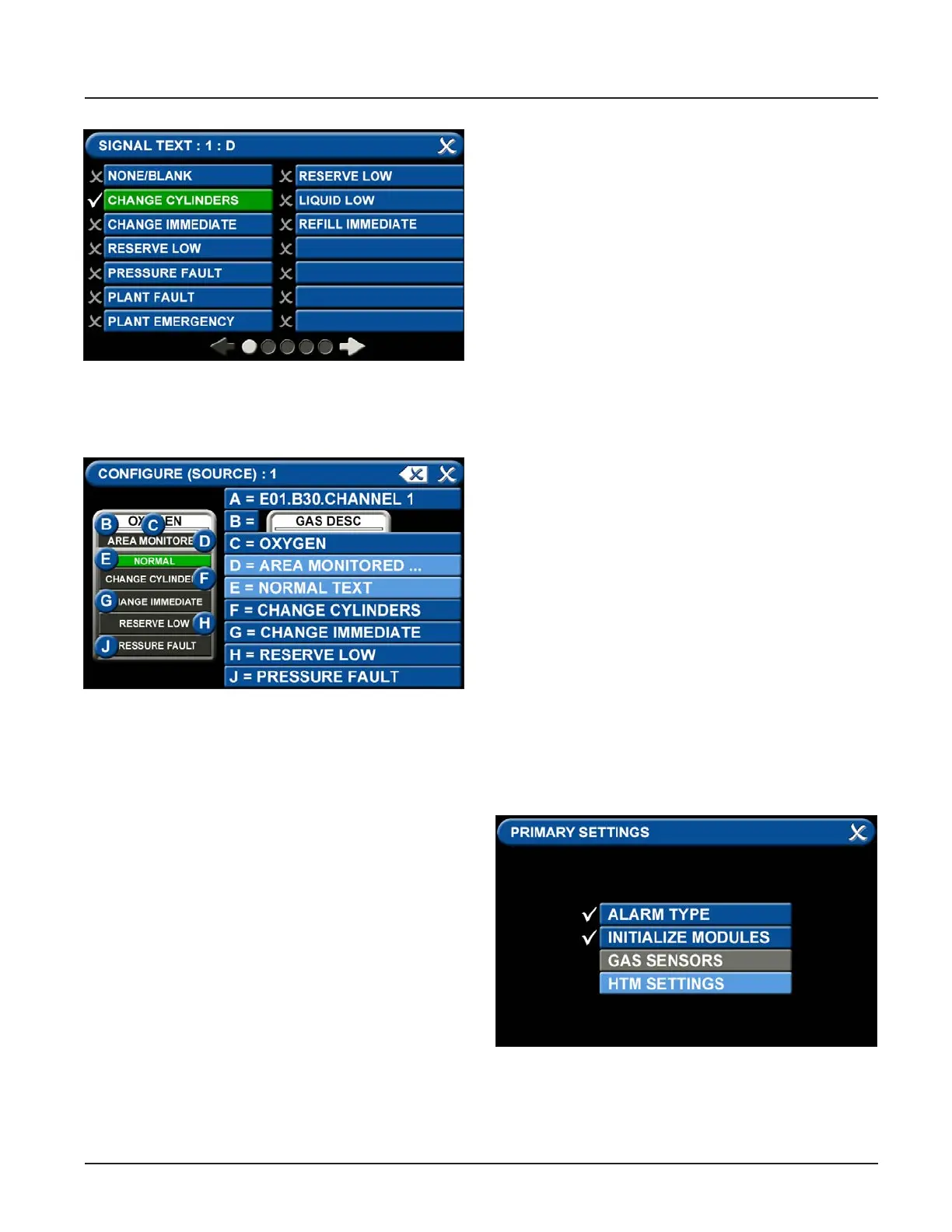
Figure 151: Signal Settings Screen
Figure 152: Signal Settings Screen
• To congure the remaining signal settings, repeat
the above steps.
• Touch the Save button when you see a check
beside your selection to save the selection and
return to the SIGNAL SETTINGS screen.
4.8 Medipoint/Shire Network
4.8.1 Medipoint Network
The Medipoint alarm system works by identifying each
individual gas channel or set or point alarm inputs with
a unique ID. The switches are hexadecimal (i.e. A corre-
sponds to 10, B corresponds to 11 etc. for the purposes
of panel identication. A channel must be set between
0 and F, 0 being OFF.
The panel with the highest ID must be set as the MAS-
TER panel, all other panels must be set as slave panels.
Therefore an alarm system may contain up to 32 pan-
els with the highest number being set as the MASTER.
An alarm system is set up by allocating a number (1 to
9) or letter (A to F) to each set of plant inputs or point
alarm inputs. Typically on a 4 gas system with point
alarms:
1 - Oxygen Manifold Alarms
2 - Nitrous Oxide Manifold Alarms
3 - Air Plant Alarms
4 - Vacuum Plant Alarms
A - Ward 1 to 4 Point Alarms
B - Ward 5 to 8 Point Alarms
Therefore on every panel where Oxygen is to be dis-
played the appropriate gas number is set to 1.
4.8.2 Medipoint Network Setup
Go to the PRIMARY SETTINGS tab (from the congura-
tion screen) to setup the HTM SETTINGS for the Medi-
point Network. (See Figure 4.153)
Figure 153: Medipoint Network Setup
•