4-46
TotalAlert Innity™ HTM Medical Gas Notication System
4107 9016 60.01
letters and numbers.
4. Touch the Save button.
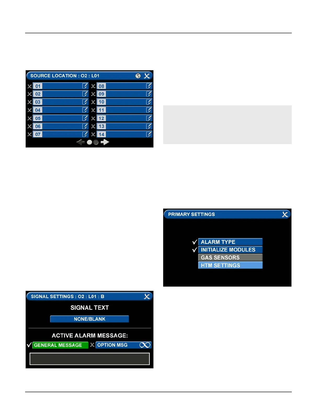
D = Area Monitored
Figure 163: Area Monitored
Touch the D = (Area Monitored) Tab
On the SOURCE LOCATION screen:
1. Touch the 01 tab. 1.
2. Using the keyboard, enter the name of the location
for the source equipment being monitored (e.g.,
ROOM 1). Enter multiple locations as needed (e.g.,
Manifold Room, Roof Top, Source Room).
3. Touch the Save button. A check appears when the
location is saved. Note: To edit the location, touch
the Pencil button.
4. Touch the X button to close and return to the
CONFIGURE (SOURCE) screen.
Each Plant (Source) badge has room for 4 signal inputs
(E-J) (Figure 4.85). The rst tab E is used to show the
alarm in “Normal” condition. The (F-H) inputs are used
for warning inputs such as “Change Cylinders” and ash
yellow when active. The last input (J) is used for the
fault condition and ashes red when in fault mode.
To select source signal input text:
Figure 164: Signal Settings Screen
1. Scroll through the options using the right and left
arrows at the bottom of the screen.
2. Touch the tab for the appropriate option, or select
a blank to create a custom alarm.
3. Touch the Save button when you see a check
beside your selection to close and return to the
SIGNAL SETTINGS screen.
4. Touch the X button in the upper right to close and
return to the CONFIGURE (SOURCE) screen.
Active Alarm Instruction:
To set facility instructions for active alarms, touch
either the GENERAL MESSAGE or OPTION MSG tab.
The alarm defaults to GENERAL MESSAGE. See
Section 4.6 for how to set up custom instructions.
4.8.4 Shire Network Setup
Go to the PRIMARY SETTINGS tab (from the congura-
tion screen) to setup the HTM SETTINGS for the SHIRE
Network. (See Figure 4.153)
Figure 165: Shire Network Setup
• To communicate with a SHIRE network, press the
SHIRE COMMS tab.