4-32
TotalAlert Innity™ HTM Medical Gas Notication System
4107 9016 60.01
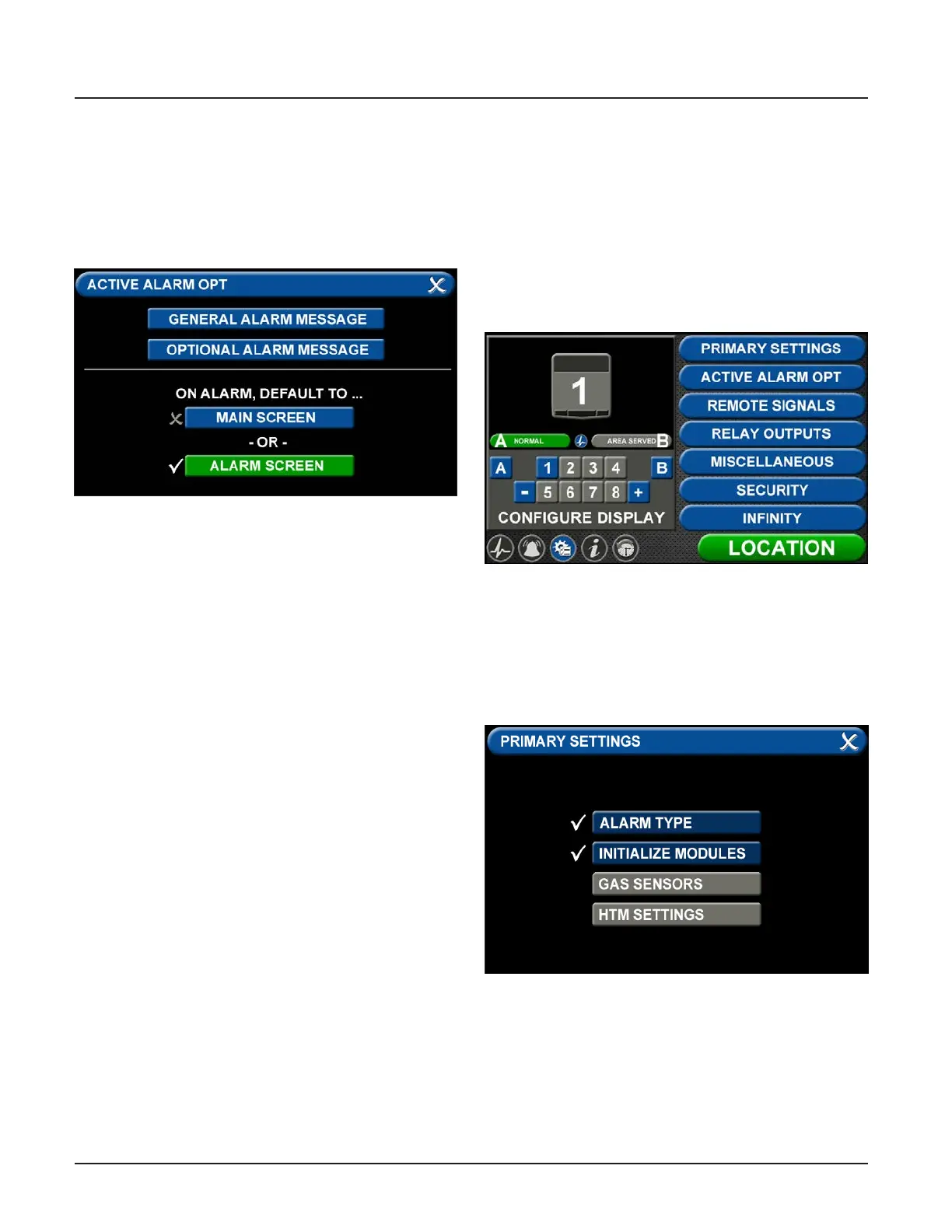
• Touch the X button to the left of the appropriate
instruction tab. When your selection appears
checked and highlighted, touch the Save button.
• This specic instruction (rather than the general
instructions) will now display on the ACTIVE ALARM
screen when the alarm is in fault status. It will also
display on the ALARM POINTS screen.
Figure 109: Alarm Message: High
• Changing the Alarm Default Screen
• The TotalAlert Innity™ Area Alarm switches to the
ACTIVE ALARM screen if the alarm goes into fault
status.
• To congure the alarm so that the MAIN screen
appears in the event of a fault, touch the MAIN
screen tab.
• If the alarm is already displaying the MAIN screen
when it goes into fault status, the toolbar will
switch from Normal to Icon and the high or low
pressure indicator on the gas badge will ash for
the gas pressure out of range.
4.7 Additional Components
4.7.1 4-20 mA Devices
To congure a 4-20mA device for monitoring, start
on the CONFIGURATION screen. Users are always
prompted to enter the password when accessing this
screen. Type the password, and touch the Enter button.
The CONFIGURATION screen displays.
Figure 110: Conguration screen
The TotalAlert Innity™ alarm is designed to allow
conguration of four gas badges using the B50 board
to monitor 4-20mA devices. The alarm must be set as
an Area panel or Combination panel. See Alarm Type
Tab in Section 4.3.2.
Figure 111: Primary Settings screen