5-2
TotalAlert Innity™ HTM Medical Gas Notication System
4107 9016 60.01
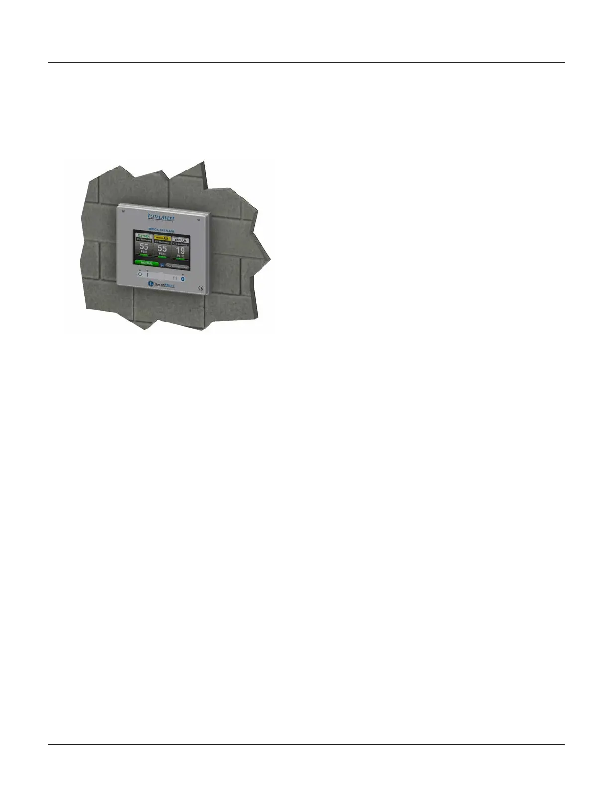
Figure 5.3: Front Panel Mounting
6. Connect the Live and Neutral wires to the terminal
block on the power supply and the Mains Earth to
the Earth stud on the backbox.
7. Place the power supply shield back in place,
ensuring that all high voltage wires are secured
behind the cover and install the four corner screws.
Central Wiring
1. For retrot of a Central alarm panel the existing
BeaconMedaes Line Monitoring contact wires
can be connected to the appropriate terminal
block locations on the B30 board along with any
Medipoint or Shire communication wires. Refer to
HTM Central Wiring Diagram (Section 3.1).
Remote Sensors
1. New TotalAlert Innity Digital Gas Sensors must be
installed to work with the TotalAlert Innity alarm
panel.
2. CAUTION: If Orice tting is not installed at the
sensor connection, ensure that the pressure on
the pipeline in the alarm area has been released
before removing any components from the
pipeline connection.
3. Remove existing pressure switch from the hospital
pipeline and disconnect eld wiring.
4. Install new digital gas sensor in the pipeline port.
5. Remove the strain relief and housing from the gas
sensor to access the terminal block. Insert eld
wiring through strain relief and housing,
connecting to the terminal block. Note the polarity.
6. Reinstall housing and strain relief and tighten cord
grip to secure eld wiring.
7. Return pressure to the hospital pipeline and check
sensor connections for leaks.
Area Wiring
1. Connect all the gas sensor wires to the appropriate
terminal block locations on the B60 board, noting
polarity. Refer to HTM Area Wiring Diagram
(Section 3.2).
5.1.3 Install Second Fix Kit
1. Install the Front display panel to the trim ring at the
bottom hinge using the screws provided.
2. Connect the lanyard to the threaded stando
on the trim ring and secure with M4 nylock nut
provided. Note: Do not tighten nut all the way, the
lanyard eyelet should move freely when opening
and closing the front display panel.
3. Connect the green Earth wire on the front display
panel to the existing Earth stud in the backbox.
4. Connect the grey RS-485 communication cable
provided on the front display panel to the power
supply.
5. Turn on the Mains power to the alarm and wait for
the alarm to boot up.
6. Setup the new alarm by referring to the Quick
Setup Guide.